Dennis Pauls, CEO, Daptech, LLC, and Ivan Masek, President, Novotechnik U.S., Inc.
When petroleum engineers drill a hole it's anything but simple. It's a job that applies several process control systems and, in the past, took three workers to handle just the control and monitoring aspects. This article describes an overview of those processes and details the technology behind the brake monitoring part of the drilling process. This is vital for safety as well as costs. Drilling operational costs would skyrocket without proper brake monitoring as described further in the article.
Similar braking and brake monitoring processes are used in many other applications including downhill mining conveyors using brakes rather than motors, large ship anchor tensioning brakes, large steel mill tensioning brakes, ski-lifts, aircraft carrier catch cable brakes, offshore drilling platform anchor systems and construction crane braking systems.
Drilling Overview
To drill for oil you need a structure to hold the pipe that connects to the drill – 12,000 feet, more or less, below. A drilling rig is essentially a crane of approximately 150' tall with a large winch, brakes, power source, and some means, such as a rotary table or top drive, to rotate the drill pipe. A typical rig has to be capable of lifting over 350,000 lbs of drill pipe. The rig's steel tower framework is referred to as an oil derrick.
This process requires extensive use of the winch and associated components, called a drawworks. The primary function of the drawworks is to control cable payout and to raise or lower the drill string. A typical 12,000 ft. drill string consists of 120 sections, called stands, of 100 ft. long pipes. The winch is usually powered by 1,000 to 1,500 HP DC electric motors for the lifting operation. The lowering operation requires large drawworks brakes to control the down speed.
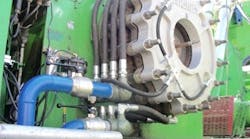
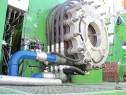
Figure 1. Drawworks brake with cooling hoses shown on a drawworks portion of a rig.
These brakes have to be capable of carrying away 2,000+ HP, or roughly 5,100,000 BTU/hr, of heat from extended "slip" action of the brakes at high loads and speeds. By way of comparison a typical home furnace might generate 100,000 BTU/hr of heat or 39 HP. Many rigs use pneumatically-applied, water-cooled disc brakes to do this job. There is usually 250 GPM of coolant running through the brakes to carry away this heat in a 900 gallon closed-loop anti-freeze system. There is no way that 900 gallons of anti-freeze can hold all this heat so a multi-plate heat exchanger is used where "fresh water" out of a 27,000 gallon drilling water storage tank is circulated in the exchanger with the anti-freeze loop. Heat is then transferred out of the anti-freeze into the large drilling water tank where it is dissipated over time or used up in the drilling process.Additionally, there is a weight monitor that measures the tension in the "dead line" of a typical 10-line block and tackle system. The non-moving dead-line is anchored to the rig platform via a load cell that is reading the tension in that line. The total weight on the blocks is obtained by multiplying that value by the number of lines in the string-up. In this example, it's 10.
When the drill bit is on bottom and the drilling process begins, the brake is used in conjunction with the weight monitor to typically keep 20,000 lbs, of the total 350,000 lbs, string weight on the bit so that it is properly forced into the material being drilled at the bottom. This can be done manually by a person, the driller, using a brake handle to continuously spool off just enough line to keep the desired weight on bit. It can also be done automatically by an automated drill system. The smoother and better controlled the weight-on-bit is maintained, the higher the rate-of-penetration is and the wear on the bit is minimized so that fewer "bit trips" are required to replace a worn-out drill bit.
Why Brake Monitoring Is Needed
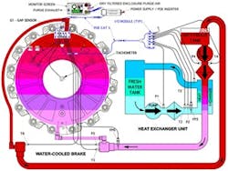
Figure 2. Brake monitor system diagram showing sensor locations.
Maintaining the optimum application of brakes while drilling can also extend the life of the brakes and, as mentioned, reduce the frequency of bit changes. This translates into substantial time and money savings.To change a drill bit on the bottom of the drill stem requires that all 12,000 ft be lifted out of the hole in 100 ft increments and temporarily stored in vertical racks in the derrick until a new bit has been installed on the bottom joint and then everything is put back in the hole. The amount of time it takes to change a drill bit is roughly 18 hours.
The "average" brake that has been burned-up from mis-use cost $60,000 to repair and results in an average of six to 12 hrs down time on the rig that can cost the rig owner between $1,800 to $2,500 per hour in lost revenue. Do the math and the result is that total brake repair cost can be as much as $90,000.
Prior to the Daptech System various pressure sensors, temperature sensors and flow meters were scattered about a rig. Several people had the responsibility to read the gauges and report issues to the driller but most did not completely understand what the gauges were telling them. During a bit-trip, removing all the pipe to get the drill bit out from the bottom of the hole, all of these people are busy on the drill platform making connections and assisting with the trip – not reading gauges.
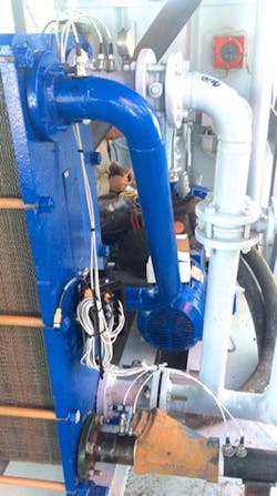
Figure 3. Eight sensors and I/O box for monitoring temperature, pressure and flow in heat exchanger.
Heavy use of brakes during tripping is when brake problems are most likely to occur. Many brake issues are only noticed when the crew suddenly sees smoke coming out of their brake. By then it is too late. The damage is done.A typical pneumatically applied, water-cooled disc brake apparatus shown in figure 1 is rated to handle 2,000 HP continuously as long as you have at least 250 GPM of a 30/70 glycol/water mix running through them to carry away the heat, and you don't exceed 170° outlet temperature, and don't exceed 60 PSI water pressure in the brake.
However, this same 2,000 HP continuous brake is capable of producing 10,000 HP at its maximum rated speed and braking torque so it can easily burn itself up if improperly used.
These brakes are very powerful and will last a long time, but their life-line is the flow of coolant that carries their self-generated heat away. To put it in perspective, a brake being used at or near its capacity can burn up in about five minutes if the coolant water flow suddenly stops from a pump shutdown or another cause. In this process the brakes don't groan or complain until suddenly smoke appears and the damage has been done.
To ensure the brakes are being applied the right amount at all times means monitoring brake pressure, coolant as well as water pressure and flow rate, coolant temperature, stroke length and rotational speed of the winch drum. Besides handling these measurements, the Daptech monitoring system has proven to be a vital tool for training operators in brake application technique.
Brake Monitoring Process
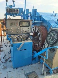
Figure 4. Drilling control console shown including brake handle which points to display. Handle angle sensor is inside housing.
Daptech's brake monitoring system consists of 15 sensors, microprocessor-based process and display controller, signal processing modules, coolant and fresh water tanks, pumps and associated plumbing.Figure 1 2 shows the three systems we are monitoring: a closed loop coolant system, a closed loop fresh water system and brake related parameters.
The Daptech monitoring system is a control system that monitors 15 sensors, applies a proprietary algorithm to the sensors data for alarms and displays the critical parameters in an at-a-glance graphical format in real time. It immediately warns the operator if something goes wrong and posts plain English alarm messages. All this information is presented at the control console where the operator will see it with no delay and no dependence on others.
It also displays the energy the control system is generating in HP and alarms with both light and horn whenever the rated HP is exceeded. Experience has shown that the single most common cause of brake failure is repeated excessive short-duration spikes in sudden brake application that can be eliminated by the operator engaging the brakes just a little sooner and managing it all the way down instead of using their traditional "drop-and-catch" method of letting the cable free-fall until the drill nears the bottom, then suddenly applying the brake.
Drop-and-catch incidents used to occur at an average frequency of 2,000 times per month. These spikes do not last long enough to overheat the coolant but they momentarily overheat the brake's copper alloy wear plates. The constant over-heating and cooling of these plates works on the metallurgy to produce cracks and it destroys the Teflon sealing material to the point that coolant begins leaking onto the friction pads which ruins them and the brake becomes so "sticky" that the rig can no longer be safely controlled.
The combination of an HP meter and alarm is the only tool available to help the operator learn the proper stopping technique to control the rig while keeping the brakes within their HP rating.
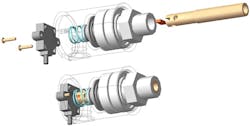
Figure 5. Exploded view drawing of drum speed sensor outside of housing and magnet, colored orange, inside.
The Closed Loop Coolant System
This system starts with a reservoir that is connected to a pump. The pump draws coolant from the reservoir and pushes it through a strainer into the inlet of the heat exchanger. During setup, the micro-controller polls the pressures on the pressure sensors when the system is operating correctly and records them as "normal" pressure values.
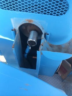
Figure 6. Drum speed sensor attached to end of aluminum cylinder and sensing angle through cylinder housing.
The micro-controller applies the following definitions to detect alarm conditions within the coolant circuit.The main screen uses the temperature, pressure and flow sensors to display Brake Coolant temperatures and flows in a simple to read bar-graph format.
The Closed Loop Fresh Water System
This system has the very large "fresh" water storage tank connected to a pump that is circulating the fresh water through a strainer to remove suspended solids from the "fresh water". This is necessary because usually the water source is dirty water from a pond. Then the fresh water is circulated through the heat exchanger (figure 3) to pick up heat from the coolant and carry it back to the main tank where that heat is stored and/or dissipated.
A microprocessor and associated circuitry reads values stored in memory devices and determines whether the system is maintaining normal status based the following definitions to detect alarm conditions within the fresh water circuit.
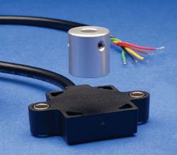
Figure 7. Vert-X 31E angle sensor, one sensor measures drum velocity and another measures brake handle angle.
The main screen uses the temp, pressure and flow sensors to display fresh water temperatures and flows in a simple to read bar-graph format.Key Brake Performance Parameters
While the fresh water and coolant control systems ensure the brake is working within an acceptable operating temperature range, the brake is subjected to operational stresses from the brake operator applying them to the rotating drill pipe. Monitoring dynamic brake performance is key to maximizing brake life, optimizing brake operator performance and minimizing drilling downtime.
There are 16 sensors used to monitor all critical conditions pertaining to the brake. This includes 15 sensors for the brake monitoring process and one angle sensor to track the brake handle position. Sensors include six pressure sensors, two flow sensors, five temperature sensors, one analog proximity or gap sensor, one angle sensor and one drawworks velocity sensor. Eleven of these sensors monitor the fresh water and coolant systems. This section is concerned with monitoring two of the pressure sensors P7 and P8, the proximity sensor, G1, the brake lever angle sensor and the velocity sensor – labeled Tachometer in figure 2.
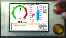
The brake application pressures monitored by sensors P7 and P8 are converted to torque values by the controller, then combined with drawworks' drum speed as measured in RPM from the Vert-X31E sensor from Novotechnik U.S. The controller displays this value as HP being required of the brake at any instant. The velocity measurement also enables the controller to post the speed the blocks are moving in feet per minute – a useful value to display so the operator can observe the speed at a glance.
This is an extremely important feature because most premature brake failure issues are caused by improper stopping technique. The power gauge provides a much needed tool for the operator to understand how hard he is working his brake and adjust his technique to stay within the brake's HP rating and still safely stop the load. The monitor screen has a gauge display that shows HP from 0 to 150 % as well as a digital display that posts the actual power being used in HP. There is also a display that posts the speed that the drawworks is moving the pipe in ft/min.
[sidebar id="5"]The 18 inch brake handle position is measured by a second Vert-X 31E sensor configured to provide a 0-20 mA output corresponding to a angle of 0 to 45 degrees for the brake handle that engages or disengages the drill brake via a pressure control signal to a valve. Being able to customize the angle sensor transfer function means Daptech can use the same part to optimize the amount of brake torque applied over portions of the handle range of motion for each application. See figure 4.
The Vert-X 31E sensors were selected as the most cost-effective and reliable way for Daptech to measure the drawworks' drum speed as well. The drum velocity ranges from 0 to 500 RPM maximum for most applications. To date there have been no field failures of this sensor.
One of the other reasons Daptech selected the Vert-X 31E is its IP 69K ingress rating which means they are completely sealed so there was no shaft seals to contend with and since they are magnetic sensors, there was no shaft to deal with either.
The Vert-X 31E output options of 0 - 10 V or 4-20 mA made it easier to integrate in the Daptech control system than a proximity velocity sensor with 9.9 V for a 1,000 RPM input. Daptech simply inserted the sensing magnet into a rotary union shown in figures 5 and 6 and attached the sensor to the union body where it can read the magnet's angular position through the aluminum housing. The sensor's embedded microprocessor calculates the velocity from the angle and a time calculation derived from a clock integrated into the sensor.
The ability of the Vert-X 31E sensor to be custom programmed by Daptech, using a programming tool called EasyAdapt from Novotechnik U.S., was also key as it allowed them to stock one sensor and program it themselves to fit any of their customer's applications. This includes custom ranges, curves, and switches.
This degree of flexibility allows Daptech to be much more responsive to the marketplace and develop solutions that work in the different situations encountered in their industry.
In addition, the gap sensor (G1) is measuring the brake stroke at every application to keep track of brake friction wear and notify the operator, via the alarm screen, when it is time to remove wear spacers for proper brake adjustment.
Output values for all the sensors as well as the power being required of the brake in HP are displayed as shown in figure 8.
Figure 8. Monitor screen detail shows brake energy in HP and other critical control parameters at a glance.
By placing all operation critical information on a single display panel available to the operator and automating alarm conditions with visual and audible alarms, Daptech has helped oil drillers improve safety while becoming more competitive in a global marketplace. Before their control system, blocks couldn't be precisely lowered when adding 100 foot sections to the existing pipe in the drill line because the ability to stop was only accurate to within 12 inches. This tore up threads and potentially could result in workers hands being pinched or even lost limbs. Now accuracy is within 1/8 inch which is sufficient to stop pipe sections from hitting.

Leaders relevant to this article:
