Jim Montague is the Executive Editor at Control, Control Design and Industrial Networking magazines. Jim has spent the last 13 years as an editor and brings a wealth of automation and controls knowledge to the position. For the past eight years, Jim worked at Reed Business Information as News Editor for Control Engineering magazine. Jim has a BA in English from Carleton College in Northfield, Minnesota, and lives in Skokie, Illinois.As natural forces go, pressure is pretty straightforward. It involves less mysterious physics than electromagnetism, it's easier to observe than thermodynamics, and its calculations are simpler than often turbulent flows. However, there are still some important aspects of pressure that must be remembered to apply its technologies properly, and this is especially important when calibrating pressure-related devices.
To reacquaint users with pressure's crucial details, two 90-minute webinars were delivered recently by ISA and Beamex. The three presenters were Hunter Vegas, project engineering manager at Wunderlich-Malec, Ned Espy, technical director at Beamex and Roy Tomalino, professional services engineer at Beamex. They decided to do the webinar on pressure because a recent Beamex survey found that about 60% of applications in process plants use pressure.
The trio reported that calibration begins with the International System of Units (SI-Units), and that international, national, reference and working standards are essential for maintaining the agreed-upon building blocks of precise and accurate calibration, process measurements and efficient performance. "When we're talking about good measurement, we're really talking about good metrology practice and data with demonstrable pedigree that can show traceability back to international standards," says Espy. "And the reason we do calibration is to bring transmitters that were installed and have drifted back to their good-as-new condition."
Basic Units and Scales
While pressure is defined as equaling force divided by unit area, Vegas reminded viewers that this simple equation can occur in some unexpected ways. For instance, if a large force is spread over a relatively large area, then the net local force is small, while a small force over a small area can have a high net local force. "Both sides of this equation need to be taken into account," says Vegas. "With tanks, a common myth is that the shape of a tank can affect the pressure at the bottom, but this is not true because 1 in. x 1 in. x 23 ft of water always weighs 10 lbs regardless of its shape, so the shape of a tank has no impact on the 10 psi pressure at its bottom. All that matters is the height of the liquid."
See Also: Calibration Gravitates Toward Cloud Technology
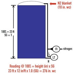
If this tank were filled with mercury, then this initial 10 psi would be multiplied by mercury's specific gravity (SG) of 13.6 to produce a pressure of 136 psi, and if a 1-psi blanket of nitrogen is added at the top to suppress fumes, then it would bring the bottom pressure up to 137 psi. "When calibrating a differential pressure (dP) transmitter that's reading pressure at the bottom, three things matter—height of the liquid, SG of the liquid and any pressure on top." Likewise, a 23-ft storage tank at 100% will read 276 inches of water column (in.wc), and a 10-in.wc nitrogen blanket will bring it up to 286 in.wc, until a compensation leg, bubbler or other device is added (Figure 1).
Figure 1: A 23-ft storage tank at 100% will read 276 inches of water column (in.wc), and a 10 in.wc nitrogen blanket will bring it up to 286 in.wc, until a compensation leg, bubbler or other device is added.
Credit: ISA, Beamex and Wunderlich Malec
The primary pressure units are atmospheres, pounds per square inch (psi), Newtons per square meter (kPa), bars that are 0.01 kPa, in.wc, millimeters of mercury (mmHg, Torr) and inches of mercury (in.Hg). "People tend to get confused because there are so many units, and then ambient pressure is also affected by altitude, temperature, humidity and even latitude," adds Vegas. "Depending how your scale is set, at sea level you may see any of these: 0 psig (gauge), 14.7 psia (absolute), 1 atmosphere, 30 in.Hg or 760 mmHg. Inches of water column are based on the weight of a 1-in. cube of water, and 27.7 in.wc equals 1 psi."
Vegas added it's also important to remember that, when using a standard orifice place in an air line, dP is multiplied by four when the flow is doubled, and dP is multiplied by nine when the flow is tripled. "Flow and dP have a squared relationship, so the dP's square root is needed to convert or relate to a given flow," adds Vegas. "This is usually done in the DCS, so if it's done in the field, you need to make sure the DCS doesn't do it again."
The Three Up-Down Test
Working in Colorado (at an ambient pressure of 12.3 psia), Tomalino first connected a Beamex MC6 documenting calibrator to the high side of a Siemens dP transmitter set up for 0-100 in.wc and a 4-20 mA output that provides a linear function of 4 mA at 0 in.wc, 12 mA at 50 in.wc and 20 mA at 100 in.wc, and has a 0.5% of span error tolerance. These levels correspond to zero, 50% and 100% of the transmitter's set operating pressure, and Tomalino used a connected, 300-psi air pressure pump with gradual venting to move the transmitter up through each level and back down through each in a three up-down test.
See Also: Long-Distance Calibration
"The calibrator just needs to know what to expect," says Tomalino. "We first zero it for the atmospheric pressure, and only have a 3-scond delay while it looks for a stable signal and automatically grabs the test point."
Tomalino reports his first test failed because its 0.59% of span was outside the set 0.5% error tolerance. The MC6 calibrator's raw data and graph showed that most error during the test occurred on its high side, and he adds it's important to preserve this as-found data to aid trending efforts. "If you can gather 10 years of calibration data, you can see if a transmitter is drifting up or down, is rock solid, or needs adjustment every time," says Tomalino. "So don't erase a test, trim and then test again."
Because the dP transmitter has HART communications, Tomalino adds that screwdrivers and potentiometers can't be used to adjust its zero and span. Instead, MC6's diagnostic service is opened, reminds the user to remove the transmitter from automatic control, adjusts its current and sensor trim to 100% at 100 in.wc, and allows it to stabilize. Next, the zero level is also typically trimmed, and when the transmitter is tested again it passes with a largest error of 0.128% of span, which documented as its as-left condition. Both as-found and as-left data sets are combined on the transmitter's calibration certificate.
Vegas adds that initial zero levels must sometimes be adjusted to account for local conditions, such as a 10-psig air line with a connected pressure transmitter (PT) line that fills with water due to condensation and may add another 10 psig, or a 20-psig steam line at 400 °F that cooks its transmitter. In both cases, the PT line needs to be relocated, or the user must account for the water's pressure by elevating its zero and 4 mA output up by 10 psig when calibrating its transmitter, and moving its 20 mA output from 30 lbs up to 40 lbs, so the DCS will read it as the originally intended 0-30 psi.
Tomalino demonstrated this procedure on a Rosemont 3051 PT set for 0-250 in.wc that equates to a 4-20 mA output, but needs to elevate its zero to account for a 10-in. wet leg, so it adjusts the transmitter to read 10-260 in.wc with 10 in.wc at the 4 mA output and 260 in.wc at the 20 mA output. "We begin with 10 in.wc, take it up to 135 in.wc and 260 in.wc at 100%, and go back down the same way," adds Tomalino. "However, if we forget to stop at 10 in.wc and vent all the pressure at the end, then the calibrator won't accept this as zero because it wasn't the input value. But we can't just go back to the 10 in.wc setpoint, so we must go up past it and then back down to it again."
This time, the calibration test failed because the 10-in. wet leg should have equated to 4 mA, but was only reading 3.9 mA. So it needed to be trimmed to zero, and was adjusted to a 0.006% of span error, which allowed it to pass the calibrator's test. All the as-found, adjustment and as-left data need to be documented and added to the calibration certificate too.
Steam Drum Level
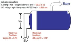
Figure 2: Water in a 36-in. steam drum at 600 psig will have a 0.787 SG, while a steam trace in its leg will be at 45 psig and 0.923 SG. Subtracting high-side from low-side readings results in a 0% level of -33.23 in.wc and 100% level of -4.9 in.wc.
Credit: ISA, Beamex and Wunderlich Malec
Vegas explains that steam drum level calibration steps include:
- Making sure interlocks are bypassed or boiler is out of service because any steam drum level transmitters have low-high level trips, isolating the transmitter, but leaving steam trace active;
- Calculating steam drum level calibration, including the zero setting of -33.23 in.wc and the span setting of -4.9 in.wc;
- Setting the zero and span;
- Returning the transmitter to service; and
- Once steam trace is at temperature and boiler is at normal pressure, adjusting the zero if necessary to match sight glass or mechanical gauge.
Tomalino again used the MC6 to calibrate level transmitter steam drum and level transmitter capillary functions for a Rosemont 3051 transmitter with isolation manifold. He adjusted the transmitter fine-tuning to reach -33.22 in.wc, observe the mA output, automatically calibrated the transmitted, and check that it passed its test. "The calculate the needed calibration, you need to know the 4-20 mA signal, and then do high pressure minus low pressure to get the 4-20 mA point needed for calibration.
Diaphragm Seals
Vegas adds that the three main types of dP seal assemblies—pad type, pad type with single capillary and dual capillary seal—can all cause problems. Pads and seals directly measure pressure, but the diaphragms in them are easily damaged or installed incorrectly. Meanwhile, fluid-filled capillaries transfer process pressure to transmitters that aren't bolted onto their vessels, but their silicon-based oils or glycerin fluids can leak and cause process incompatibility; become viscous and slow their response due to low ambient or process temperature and pressure; or boil in low vacuums and high temperatures and ruin their applications.
"Process heat can cause liquids to expand and cause the readings on a transmitter to rise, but changing process temperatures will generate zero shift errors in the transmitter," explains Vegas. "Also, a larger seal will be more sensitive and able to read lower pressures, but it's also more prone to zero shifts due to process temperature variations. Similarly, wider capillary tubes respond faster, especially if fill fluid is viscous, but their higher volume results in more zero-shift issues from ambient temperatures."
In addition, single-seal capillary installations are subject to zero shifts due to changing process temperatures, and they only work on vented tanks, though they can work on pressurized tanks if the low leg is tubed up. They'll also likely need purges to keep out condensation.
Likewise, dual-seal capillary tubes can also create zero shifts due to ambient temperature changes, which may be offset if the capillaries are the same length. They also may be subject to zero shifts due to process temperature changes, unless both seals see the same process temperature.
"Seals are fragile and expensive, and need to be checked before they're bolted down, and you always need to be aware of ambient temperature," explains Espy. "It's also important to address up-front how testing and calibration will be performed to avoid big headaches. And venting at capillary seals is critical. Flush rings are useful for venting and applying calibration pressure, and this means the seal doesn't have to be unbolted." He adds that dP seal calibration steps should include:
- Isolate both seals from process using flush rings;
- Be sure both seals are at their normal position and elevation
- Vent both seals to atmosphere using flush rings; record the current 4 mA reading as found
- Apply span pressure on the high seal and record the current 20 mA reading as found;
- Vent both seals and adjust the transmitter to read 4 mA as left;
- Apply the span pressure to the high seal and adjust the 20mA point as left;
- Close vents and return the seals to service.
Tomalino adds that a tank with a 0-25 in.wc level range and 4-20 mA transmitter output may have a -28.46 in.wc to -3.46 in.wc pressure based on its process' SG, capillary fill fluid SG and a long capillary vertical distance to the low-side sensor, and all of these need to be compensated for in its calibration and trim.
"This kind of problem can be mind-bending for technicians, so you need to break it into chunks to conquer it," says Tomalino. "You need to test and pass the level transmitter and then test and pass the transmitter with the capillary. The lower trim pressure is closer to zero, so you capture the as-found data for the 0-5 mA input. The pressure calibration shows the pressure coming in and the current going out, so you do the lower, enter -3.46 in.wc, and send it over. Next, you do the upper, vertical pressure, and enter -28.46 in.wc. Then, you increase pressure, check for hysteresis, do an up-down test, see that it's passed, and store and save the results."
[Editor's note: This article is based on two webinars on Oct. 2, 2014, and Feb. 19, 2015, which were organized and hosted by the ISA and Beamex. They can be viewed in their entirety below


