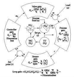
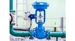
Figure 1: If the process is non-linear (Gp varies with load), the gain product of the loop (LG) should be held more or less constant by compensating for the variation in Gp by using a non-linear valve with inverse Gv non-linearity.
Q: Is there some general rule on when we should use =% (equal percentage) and when linear control valves? I know that the determining factor is the inherent flow characteristic, the flow vs. lift at constant pressure drop, or something like that. I do not know what this means, because constant valve pressure drop rarely exists except in the ideal conditions in the manufacturer's test lab.
Nenad Tripkovich, Serbia
[email protected]
A. The selection goal is control loop stability. This we obtain by making the loop response to load changes as linear as possible (keeping the loop gain more-less constant). The gain of any device is the ratio of its output divided by its input. The loop gain (LG) is the product of the gains of the loop components, the process(Gp), sensor (Gs), controller (Gc) and valve (Gv). Tuning the loop means that if our goal is quarter-amplitude damping, we adjust the controller gain (Figure 1) so that the loop gain (LG) will be about 0.5.
LG = (Gp)(Gs)(Gc)(Gv) = CPG(Gc) ~ 0.5
Linear valves: If the total process gain (TPG = (Gp)(Gs)(Gv)) is more or less constant (does not change much with load), linear valves should be used. In a linear (constant gain) valve, a 1% change in lift results in a 1% change in flow (Gv = 1.0). TPG is acceptable if it stays between 0.5 to 2.0, as the load varies between its minimum and maximum limits. Linear valves are used in most applications except heat transfer (temperature control).
TPG = (Gp)(Gs)(Gv) ~ 0.5 to 2.0
Non-Linear Valves: If the valve gain rises as the valve opens, its characteristic is called equal percentage (=%) and if its gain drops as it opens, it is called quick-opening (QO). Special, custom-made valves can provide other non-linearities, for example, having gains that are the inverse of the pump curves. Therefore, compensation is provided by using an inverse valve characteristics (Gv = 1/Gp), so that the installed characteristics of the total process will be more or less linear (TGP = 0.5 to 2.0). Naturally, Gv can never be the exact inverse of Gp, but as long as the selected valve characteristic keeps the TPG within 0.5 and 2.0, instability and limit cycling can usually be avoided by good controller tuning (assuming TGP = 1.0 when adjusting Gc).
Equal Percentage Valves: Equal percent (=%) valves are used on heat transfer processes because in case of heat transfer (temperature control), when the heat load is low, the heat transfer surface area available to transfer that heat (load) is large. As a consequence, at low loads the heat transfer is efficient; the process gain (Gp) is high. As the load rises, the same heat transfer area has to transfer more and more heat and therefore its efficiency (the process gain) drops. To compensate for this, we need a valve whos gain rises with load (=% one). For example, if the selected =% is say 3%, flow will increase 3% for each 1% increase in lift. Therefore, the higher the load (flow), the higher this 3% quantity becomes and, therefore, the valve gain (Gv) rises with load.
Some will also use =% valves when using constant-speed centrifugal pumps to transfer fluid through long pipes. They do that because at low flows, when the pressure drop in the pipe (ΔPpipe) is small, most of the inlet pressure is burned up in the valve (ΔPvalve), so a small change in lift results in a large change in flow (Gp is high). As the load rises, the pipe drop (ΔPpipe) also rises, and therefore, less pressure drop is left for the valve, so Gp drops. This method of compensation is wrong because it is at low flows one should not burn up all that energy in the form of valve pressure drop (ΔPvalve)! Instead, variable- speed pumps providing constant valve pressure drop and linear valves should be used.
As you can see, you asked a complex question, which I could answer only briefly here. So if you need an in depth explanation, see Chapter 6.7, starting on page 1154 of Volume 2 of the Instrument Engineers Handbook, where Table 6.1g lists the selection of valve characteristics for many applications.
Béla Lipták
[email protected]
A. Use a linear valve when controlling flow, liquid level, pressure and composition, and an equal-percentage valve when controlling temperature.
In over 60 years working with control loops, almost all the cases where I had to change valve characteristics, I have been replacing equal-percentage with linear.
F. Greg Shinskey
[email protected]
A. In order to make the control as stable as possible, you want the loop response to be as linear as possible. (If you put the loop in manual and move the output 10%, you want to see the same 10% change in the measurement regardless of whether you moved the output from 10% to 20% or from 70% to 80%. If the response is nonlinear, it is difficult to tune the loop because a gain that works great at low valve opening will not work as well as the valve opens further.
Let's say you are controlling flow with a valve on a long pipe fed by a centrifugal pump. When the valve first cracks open, the flow is very low, the pump discharge pressure is high, and the line loss is very small. In this case, the control valve is taking nearly all of the pressure drop, and a small change in valve position will result in a big flow change.
Now consider the same when the valve is 80% open. In this case, the flow is high, the pump discharge pressure will have fallen, and the line loss will be much larger. Now the pressure drop across the valve is much lower, and a small change in valve position will not change the flow very much at all.
In this case, an equal percentage valve is the appropriate choice because the characteristic of the valve offsets the effect of the piping.
When the valve first opens a 5% change will not move the valve much. However when the valve is more than 50% open a 5% change will move the valve a great deal more. This inverts the effect of the piping and creates a more linear response for the loop.
Now consider a case where you are controlling flow, but the pipe is short and the pump has a fairly flat flow curve. The valve is now taking the full line drop regardless of its position. In this scenario a linear valve trim would be a better choice because a 5% valve position change will affect the flow consistently regardless if the valve is barely open or nearly fully open.
P. Hunter Vegas, PE
[email protected]
A. Linear or =% valves have very practical applications not just theoretical ones. The exact conditions can be found in many references, for example, Emerson's Control Valve Handbook. http://www.documentation.emersonprocess.com/groups/public/documents/book/cvh99.pdf
I came across an application on startup where the =% valve gave poor control because the piping pressure drop was low. I had to do an inverse characterization in the DCS (which amounted to gain scheduling). In other words, the process piping was larger than it needed to be.
Two classic examples of linear valve applications:
- A bypass valve around a heat exchanger for temperature control
- A trim valve in parallel with a larger main valve.
Simon Lucchini
[email protected]
A. In general, control valves with an equal percentage inherent characteristic are used to produce a linear installed characteristic in process control. Such an installed characteristic in flow vs. lift for control valves can be mathematically derived and has been published in text books on process control.
Some control valves are provided with custom-made trims so that the pump curve is built-in. This provides high loss coefficients at low flows and low loss coefficients at high flows, and eliminates the need for parallel valve operation and therefore reduces maintenance while increasing reliability and controllability in process control. Boiler feed water valves are an example.
Gerald Liu, P. Eng.
[email protected]
