
How can self-regulating pressure regulating valves be made to fail closed?
This column is moderated by Béla Lipták, automation and safety consultant and editor of the Instrument and Automation Engineers' Handbook (IAEH). If you have an automation-related question for this column, write to [email protected].
Q: We are going to install self-regulating, pressure-regulating valves (two valves in series) at the inlet of a new air cooler skid to reduce the upstream pressure from 125 Barg to 5 Barg (from 125 Barg to 50 Barg and then from 50 Barg to 5 Barg). Due to safety and economic issues, the process engineer asked us to provide these two self-regulating valves to have closed failure positions. I’m concerned about the availability of a standard valve that can regulate the downstream pressure while having a closed failure position.
The pipe size is 3 in., the Cv is 5.86 calculated on maximum flow rate of 40,250 Kg/hr and differential pressure (DP) of 55 Barg. The fluid is water. We have no electronic control system in the plant, so we have to install the self-regulating valves.
Could you please advise?
Ragab Abdel Fattah.
[email protected]
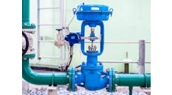
A: When a device uses external energy (electric, pneumatic, hydraulic) for its operation, its failure position is the position that it takes when the external power supply fails. In the case of self-regulated devices such as let-down pressure regulators, there is no external power supply and we define their failure position as the position they take if one of their components fail. If the diaphragm or the downstream control line breaks, the regulator (Figure 1) usually opens, and when the spring breaks, they usually close. Therefore, if you are concerned about over-pressuring the downstream side of the regulators in case of diaphragm failure, you should place a relief valve on that side.

Figure 1: The components and operation of the basic pressure regulator result in the failure modes and positions shown in Table 1.
I assume you have two valves in series because you need cavitation prevention. Cavitation occurs when the vena contracta pressure inside the valve (Pvc) drops below the vapor pressure of the flowing fluid (Pvc < Pv). The supplier will provide you with the pressure recovery coefficients of the regulators (FL= ∆P/[P1-Pvc]1/2) and with the cavitation coefficients (Kc = ∆P/(P1-Pv)). Therefore, if you plug your vapor pressure (Pv) into these equations, you can calculate the vena contracta pressure the regulators will have, and as long as this pressure stays above your vapor pressure (Pvc > Pv) at maximum flow and temperature, you will be OK. On the other hand, if Pv drops below Pvc (at maximum flow and temperature), you have to select a valve with higher FL and Kc. One such anti-cavitation trim design providing the characteristic A in Figure 2 is shown in Figure 3.
Béla Lipták
[email protected]
| Regulator types | Main diaphragm ruptures | Main spring breaks | Downstream control line breaks | Pilot diaphragm ruptures |
| Basic self-operated regulator | Opens | Closes | Opens | N/A |
| Self-operated pressure-loading regulators w/downstream bleed | Closes | Opens |
Opens |
Opens |
| Pilot-operated two-path regulator | Closes | Opens | Opens | Closes |
| Pilot-operated unloading regulator | Closes | Opens | Opens | Closes |
A: The option is to install a regular fail-closed pneumatic control valve with a pneumatic controller. This arrangement could probably be sized to handle the letdown in one step and would fail closed on loss of air.
Hunter Vegas, PE
[email protected]
A: Dropping pressure with a severe service control valve (not a self-regulating pressure valve) from 125 barg (almost 1,875 psig) to 50 barg (almost 750 psig), a 60% drop, is difficult because a trim loss coefficient (k-factor) of about 16 is required. I don’t think any self-regulating pressure valves can do that.
Please think about the loss coefficient of a drilled hole, typically 1.5 at the most, and you will need about 16/1.5 or 10 stages of drilled holes at least to drop 125 barg to 50 barg. At present, with the best of technology nowadays, seven drilled-hole cages is the maximum number of stages that any control valve manufacturer can implement because the number of stages for drilled-hole cages is limited by the size of the valve flanges. Furthermore, the individual resistances of stages in series within a control valve don’t add up in arithmetic progression to form the overall trim loss coefficient, but in geometric progression approaching an asymptotic limit. In other words, 10 stages of drilled-hole cages in series don’t give us an overall loss coefficient (or resistance) of 10x1.5 or 15, but a number substantially less than 15, such as 11 or 12, depending on the size of the hole in each stage.

Figure 2: Solid lines show the pressure profiles in the valve without any correction and the dotted lines show the results of five ways of protecting against cavitation by increasing the vena contracta pressure (Pvc).
Dropping pressure from 50 barg (almost 750 psig) to 5 barg (almost 75 psig) is even more difficult because that is a 90% drop, and is even further away from the critical pressure drop limit (which is about 50%, depending on the nature of your process medium). I have experienced in fixing a problem of steam pressure drop from 600 psig to 50 psig, the vibrations of the valves owing to shock waves in the valve exit, eventually rendering the valves permanently shut. To give you an idea of proper control engineering, to vent steam from 50 psig to atmosphere, a control valve with 36 stages of resistance is required (not in drilled-hole cages, but in right-angle turns in discs) to cope with noise regulations. I don’t think any ordinary self-regulating pressure valve can drop 50 barg to 5 barg. (“Ordinary” here means valves with drilled-hole cages).
Regarding the failure mode, you can specify fail-closed and it can be implemented. But you have to specify exactly what medium will fail, i.e. power failure or signal failure. In the case of a self-regulating pressure valve, power failure is the upstream process pressure loss, while signal failure is the impulse line pressure loss (which can also due to upstream process pressure loss or tube burst). With an accumulator (air or hydraulic, depending on your requirements), any valve can be designed to fail closed or fail open. However, I don’t know any self-regulating pressure valve(s) having fail-closed functionality yet. I wouldn’t say they don’t exist. Please discuss further with your process engineer on engineering, not commercial, requirements first. I was also a senior instrument engineer in one stage of my career.
Gerald Liu, P. Eng.
[email protected]
A: Self-acting pressure regulators can achieve specific fail positions based on the spring/diaphragm. You can specify in the datasheet failure mode and direction. If you don’t specify, it will assume default position. In short, you can implement the process requirement.
Guha Debasis
[email protected]
A: Self-regulating pressure regulators are mechanical devices and hence do not have a fail-safe feature. The best you can do to address the particular concern is to install safety relief valves (SRV or PSV) immediately downstream of the pressure regulator. Hence, you can install an SRV with a setpoint of 51 barg after the first regulator and a second SRV with a set-point of 5.5 barg after the second regulator.
A new device is available from ITTBarton, however, it can withstand a maximum input pressure of 6.9 barg.
Raj Binney
[email protected]


Leaders relevant to this article: