Key Highlights
- Proper signal filtering at the source minimizes aliasing errors and improves the accuracy of digital data used for control and analytics.
- Teaching filtering concepts through visual simulations and hands-on exercises enhances understanding of time constants and their impact on process control.
- Incorrect damping settings, such as maximum damping on a vessel experiencing fluid sloshing, can hide dangerous process fluctuations, risking safety and control integrity.
This is the first in a new series of discussions on ensuring data integrity for process control and industrial automation systems with Mike Glass, owner of Orion Technical Solutions. Orion specializes in instrumentation, automation training and skill assessments. Glass is an ISA-certified automation professional (CAP) and certified control systems technician (CCST III) with nearly 40 years of instrumentation and controls (I&C) experience across multiple industries.
Greg: Mike, there's been considerable discussion lately about using advanced technology and artificial intelligence (AI) for predictive maintenance and improved plant control. Since good data is paramount to good process control, process safety and accurate analytics, I’d like to discuss issues related to data quality and integrity in I&C systems.
Mike: Let's start by talking about signal filtering, which is both a logical first step and one of the biggest problem areas.
Greg: Describe input signal filtering and some of the problems it causes.
Mike: Instruments inherently experience noise from process fluctuations and physical phenomena such as differential pressure (DP) variations in flow measurements, surface turbulence in level sensors, induced electrical noise and others. Unfiltered transmitter noise can lead to aliasing errors, and degrade process control performance, safety systems and analytics. Even the most sophisticated control system or AI can't overcome poor quality input data.
Greg: What are some practical examples of how improper filtering affects different systems?
Mike: In process control, inadequately filtered pressure fluctuations in a DP flow measurement might cause the PID loop to continually adjust the control valve, potentially causing premature valve failure through excessive cycling, among other problems. Excess filtering can make control difficult or even impossible.
For process safety, insufficient damping creates nuisance alarms and trips, while excessive damping could prevent safety systems from responding when truly needed.
With data analytics, poor filtering leads to corrupted data, leading to phantom patterns that don't reflect actual process conditions, and incorrect conclusions.
Greg: Can you talk more about the aliasing problems you mentioned?
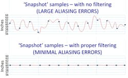
Mike: Consider a level transmitter connected to an analog input sampling at 100 msec intervals. Without proper damping, the analog card captures random snapshots of the noisy signal at each sample interval. Once these digital sample snapshots are taken, the errors become permanently embedded in the digital data. If that noise is properly filtered at the source (the transmitter), aliasing errors are minimized, and the digitized data will better represent the actual measurement.
This example illustrates aliasing errors on the top plot, and shows how properly filtering noise at the transmitter will prevent feeding aliasing errors into the controller.
In some cases, when harmonics of noise frequencies align, it can produce deceptive patterns that can be misinterpreted by controllers, intelligent systems or personnel viewing the misleading data.
It’s also important to note that, in addition to properly filtering noise, it’s sometimes necessary to consider the sample rates and communications rates of field equipment. Many times, they’re set excessively slow by default, and don’t factor in the needs of the loops they’re measuring.
It's worth mentioning that many input cards have additional notch filtering specifically for electrical noise (especially in 50/60 Hz band) to help reduce induced electrical noise on the signal line after the transmitter.
Greg: What are your thoughts on filtering in the controller via a filter block or similar logic function?
Mike: I refer to this practice as “smoothing” instead of filtering because it’s different from filtering out noise. Filtering after aliasing errors are embedded is just smoothing out the bumps to make them appear flat. Once an error is digitally captured (the sampling snapshot), it can’t be effectively removed by smoothing with downstream filters.
To smooth out aliasing errors, downstream filtering must be set very slow (high time constant), and this excessively filtered PV will likely lag behind the process during faster transients. This is likely to negatively impact process control/tuning, as well as process safety, and hinder using the data for analytical purposes.
It’s also possible to filter signals at the analog input card for some control systems. The technical details vary, but in some specific situations, such as when filtering occurs prior to digitization/sampling, it can yield decent results.
Greg: I’ve observed these mistakes as well. Why do you think this happens so often?
Mike: The primary reason is because controller-based filtering is legitimately easier to track and control—a valid concern since field personnel often make mistakes when setting transmitter damping.
Some engineers feel it’s easier to have a zero-damping policy and perform all filtering inside the controller, but that can be problematic in many cases, especially on fast loops with high levels of noise.
Greg: How do you teach the concepts of filtering and damping?
Mike: I start with the basics of observing good and bad filtering directly to visualize why it happens, and then visualize the concepts as much as possible. I add any necessary factoids or deeper theory after to visualize the core concepts, and have good context on how and where the information is used.
Typically, I make filtering adjustments to a system, while observing the changes with a simulation and then on our physical training stations.
The filtering discussion naturally leads to questions and a discussion about time constants, so I let that play out naturally via questions and discussion during the lab exercises. I find answering a question or expounding on a detail during a lab results in better retention and application of the topic, so I build that natural learning flow into all our courses.
Get your subscription to Control's tri-weekly newsletter.
To describe a first-order system, in which time constants are based, I typically use simple examples, such as placing a thermometer at room temperature into a cup of 200 °F water. At first, the temperature screams upwards because of the large differential temperature. However, as the thermometer gets closer to the water temperature and the difference reduces, the rate of change slows. The result is the exponential curve we all know. Then, we test sensors with different sheath/thermowell thicknesses to visualize physical damping factors.
One lab exercise students perform to conceptualize the math of time constants is using an RTD simulator fed to an RTD transmitter, and do the following:
- Set transmitter damping (time constant) to 5 seconds. Then set the initial calibrator output to 0 oF, letting it stabilize.
- Then, set the RTD simulator to 100 oF (conveniently 100% in this example) and observe the response.
I do this in the up and down direction several times, and ask the students to predict and record where the reading is at each 5-second interval. I repeat this exercise with different time constants until we can predict the readings at various time intervals.
I also ask the students what would happen if I only waited 15-20 seconds to record or adjust a calibration reading on that transmitter. Of course, the answer is that it will introduce a notable error into the calibration.
Over the years, technicians admit they’ve likely been introducing errors into their calibrations by not waiting long enough between checkpoints. Ironically, it’s one of the most common causes of calibration mistakes.
Because those damping settings are so important in any I&C related work, I always tell people to do two things anytime they connect to a transmitter to perform calibrations, testing or troubleshooting:
- Record the initial damping (time constant setting), and raise the question of whether it seems excessive or inadequate.
- Wait 10 times the damping value before taking any readings or making any adjustments to ensure the system is fully stable. I refer to this as “10-X.” For example, if damping is set to a 5-second time constant, wait 50 seconds. Waiting seven- or eight-time constants is adequate to ensure any errors are below the range of perception of typical calibration equipment, but the 10-X method” is easier to remember and easier for most people to calculate.
Greg: What approaches do you suggest for setting damping on a field transmitter?
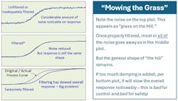
Mike: There are several approaches depending on what equipment is available and on details such as input card sampling rates, comms bandwidth, trending capabilities and so forth, but the core concept boils down to what I refer to as “mowing the grass without excavating the hill.” If we add enough filtering that it slows the overall response (excavating the hill), it’s likely to cause problems.
I explain that the objective is to cut the grass (noise) as short as possible without changing the shape of the hill (actual process response). It sounds simplistic, but it works, especially after they see it in action.
Once someone understands time constants and how they affect filtering, I like to have them work on some actual filtering scenarios. I usually teach this part via the bump-test method on a simulator of some kind or on a non-critical loop that’s safe to tinker with. It’s good for students to observe how increasing damping of an instrument could throw a loop into oscillations or result in dangerous undetected failures in process safety or SIS systems.
One common oversight is assuming the data has minimal noise based on what’s shown in the PLC/DCS raw input. That data was already processed, and some (or a lot of) smoothing has already occurred, even with no damping inserted. In some cases, input sample rates and comms simply aren’t fast enough (for various reasons) to avoid aliasing and other digitizing problems in the controller data. In those cases, one may need to utilize field test equipment on the signal line, such as chart plotters or recording o-scopes to see the noise clearly enough to properly adjust filtering. This is also helpful in differentiating any AC or induced noise from process, sensor or physical noise sources.
Once they’ve recorded baseline trends for typical system responses to applicable upsets and transients, the students observe the shape and slope of the responses, which I refer to as the hills, as well as the amount of noise present, which I refer to as the grass on the hill.
Often, they measure and record the process deadtime/lag and process time constants, and notice other process characteristics that skew the hill, such as integrating or runaway processes versus true, first-order systems. Since damping/filtering is critical to good process control, I set up the associations to those concepts, even on courses where I’m not actually covering process control, depending on students’ backgrounds, jobs and needs.
For my I&C classes, I built a simulator that allows us to test and properly dampen the noise from numerous editable example scenarios. Here’s a link to the damping simulator that includes a tutorial with practical challenge exercises, as well as the ability to do freestyle, open-ended problems and questions.
As part of the damping exercises, we also cover several bad-case scenarios, so they get to visualize what happens to tuning, safety systems and data relevancy when you apply too little or too much filtering. Often we must simply find a compromise between noise and response speed.
Greg: You mentioned some dangerous scenarios that you witnessed related to damping earlier. Can you share an example?
Mike: While assessing an experienced instrument technician, he proudly described recently "fixing" a level transmitter on an offshore platform. Heavy seas were causing fluid to slosh in a horizontal separator vessel, triggering alarms. His solution was to set damping to maximum (60 seconds), which completely smoothed out the reading. The problem he overlooked was that the vessel was still experiencing dangerous high and lows, but the process safety system saw nice smooth trends with no alarms or trips.
After our discussion, the technician immediately called to have the damping value set back to the appropriate value. This isn't an isolated incident. I've seen this exact scenario across multiple facilities, even on SIS devices. It's a frequent assumption. This is a perfect example of how a lack of training and development lead to misunderstandings of seemingly minor details that can lead to major controls or safety issues.
Greg: That’s certainly a sobering thought, and shows why it’s important for us to keep covering these things. I appreciate your input and insights, Mike, and look forward to our next chat as we continue to work our way through the I&C data path. Let’s start talking about the issues in the digital parts of the data path next year. Right now, here are some process control alerts. A filter time less than largest time constant in a loop becomes a deadtime in a first-order plus dead time approximation. The ultimate limit to the peak and integrated error for a load disturbance is proportional to the deadtime and deadtime squared, respectively, for a large process time constant. The actual practical limit to the integrated error is proportional to the PID reset time plus filter time. Studies with a reset time much larger than optimum have falsely concluded that the effect of a particularly large filter time is negligible.
What’s exceptionally dangerous is a large filter time in a process with a runaway response due to positive feedback (e.g., highly exothermic reactors) that narrows the window of allowable PID gains, where too low a PID gain causes a rapid runaway more disastrous than the oscillation from too high a PID gain. Also, what’s not realized is that, if the filter time is larger than the process time constant, increasing the filter time enables a larger PID gain and excessive smoothing, giving a false sense of achievement. I was at a conference where the presenter said his company almost didn’t allow his presentation because the benefits were so significant they shouldn’t be shared with competitors. His study showed a filter time much larger than the process time constant, where the controlled variable response to a load disturbance was so attenuated he considered it a breakthrough. He hadn’t plot the unfiltered process variable to see that what was really happening was a much larger peak and integrated error. I’ve found that minimizing damping and filter settings is critical for pressure and surge control. For much more on my experiences with damping, signal filters and measuring time constants from sensors, read my Control, September feature article “Route to best process control destination.”
Mike: I greatly enjoy collaborating on these talks. Hopefully some of these insights will prove helpful to your readers, and help their plants run better and more safely.
Top 10 signs your company has downsized too much
- Consultations with yourself are the norm.
- It’s impossible to create a normal distribution of employee performances.
- None of your co-workers are employed by your company.
- The signatures on your “retirement” plant photo barely fill 25% of the border.
- The common reply to task requests is “yeah, whatever.”
- The new corporate phone directory is distributed on a 3x5 note card.
- The human resources department is a bulletin board in the lobby.
- You call in, request to be transferred to your bosses' secretary, and get forwarded to yourself.
- The "auditorium" for large corporate meetings is now the cubicle next to you.
- Retirement package" is a box with personal belongings from your desk.
About the Author
Greg McMillan
Columnist
Greg K. McMillan captures the wisdom of talented leaders in process control and adds his perspective based on more than 50 years of experience, cartoons by Ted Williams and Top 10 lists.


