There are several techniques that enhance PID, termed advanced regulatory control. These were developed in the 1930s-40s and include reset feedback to prevent windup, override to prevent excessive or unsafe conditions, feedforward, and ratio to correct an anticipated upset. Also, these include cascade, which we discuss in this installment of the series. In addition, they include decouplers, gain scheduling, output characterization and various forms of model-based adjustment. These techniques remain very useful today.
Cascade control bottom line
The bottom line of cascade control means: if you notice the process influence of a controller can also be affected by other influences, then you must control that process input. For example, if the controller adjusts the valve to change flow rate, but line pressure might also affect the flow rate, then control the flow rate to a setpoint.
If there’s another process variable that’s an early indicator of what will eventually happen to the primary controlled variable (CV), then control that variable. For example, tray temperature in a distillation column is a leading indicator of product purity. Instead of manipulating reflux to control the delayed and lagged purity measurement, you can manipulate reflux to control a tray temperature.
In cascade control, the output of the primary (supervisory) controller is the setpoint for a secondary (inner) controller. The secondary loop needs to be faster than the primary loop for this to have an advantage. Some use the rule that: (?+3?)_inner3?)?_outer.
Proportional-only control is often fully satisfactory for the inner loop. The integrator in the primary controller can compensate for moderate offset. Tune the inner loop first, then tune the primary with the secondary in “auto.” The inner loop is just part of the process to the primary controller.
You still need feedback from the primary controller due to calibration errors of secondary sensors, as well as unmodeled and less than ideal effects that can take place.
Cascade control reflux
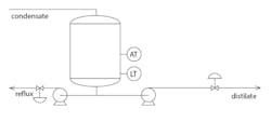
Figure 1 represents part of a distillation process. It’s a reflux tank that receives condensed vapor from a distillation column. The vapor is purified by the sequential tray-to-tray “boiling” in the column. The distillate condensate enters the top of the tank. Some condensate returns to the column as reflux to control purity of the distilled product. The residual portion of the condensate is distillate product.
The tank needs to have the liquid level controlled—the level transmitter (LT) reports the level. The analysis transmitter (AT) is probably located in the vapor line exiting the column for faster response. However, for convenience, the diagram shows the AT on the tank. The AT commonly reports impurity in the distillate, not its purity.
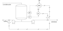
Figure 2 illustrates a primitive control scheme. The analysis recording controller (ARC) receives AT information, and sends a signal to the reflux valve. The level indicating controller (LIC) listens to the LT and sends a signal to the distillate product valve. If both valves are air-to-open (fail-closed), abbreviated as ATO or FC, then the LIC must be a direct-acting controller. If the level goes up, the controller needs to open the valve by increasing its output. The ARC must also act directly. If the impurity increases, the ARC needs to increase its output to open the reflux valve, and send more reflux back into the column to wash the impurity back toward the bottom.
One issue is the AT provides delayed impurity information. Whether on the vapor exit or tank liquid, the AT might be a gas chromatograph with a 15-minute cycle time. A temperature measurement on a tray near the top of the column provides an early indication of the impurity level. If the impurity rises, the tray temperature will rise. The temperature is easy to measure and responds immediately, but it’s not an exclusive measure of impurity. The temperature also depends on the column pressure and other components in the product.
This situation represents the second justification for a cascade strategy: if there is a leading indicator, control it.
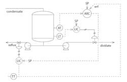
Figure 3 illustrates a cascade strategy. The temperature indicating controller (TIC) looks at the column temperature transmitter (TT), and adjusts the reflux valve to maintain the temperature at the setpoint. The ARC is now promoted to a supervisor, and sends the setpoint value to the TIC. The ARC has the primary responsibility, and the TIC looks at a secondary variable.
The ARC is now “talking” to the TIC and saying, “TIC, your temperature setpoint is 87 °C.” The ARC role has substantially changed. It’s now reverse-acting. If the impurity goes up, then the target temperature for the tray must go down. The ARC action also needs to change from direct to reverse. In other cases, the action might not change.
The external reset feedback (ERF) signal to the ARC is the actual temperature. If the ARC is in charge, then it will match the ARC output. The ERF signal isn’t required. It may only infrequently provide a benefit that matches its complication.
Combined cascade and ratio control
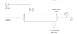
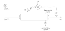
Figure 4 illustrates a steam-heated shell and tube heat exchanger. Cold process fluid enters on the left, flows through tubes, and exits on the right. Steam enters via the shell side and condenses on the tubes. The condensate leaves at the bottom, with outflow controlled by a steam trap. Non-condensable gases in the steam build up in the shell, preventing the steam from seeing a portion of the tubes. Those gases must be vented. The diagram shows this process as a thermistor-type vent.
The objective is to adjust the steam inflow to control temperature. Inflow process flow rate and temperature, changes in ambient losses, and cycling of the non-condensable gas discharge all require continual steam valve adjustment.
Figure 5 illustrates the primitive control scheme. The TIC is talking to the valve and saying, “Valve, go to 63% open.” If the valve is ATO, then the TIC must act in reverse. If something makes the temperature rise, the TIC must reduce its output to move the valve toward a less open position.
One issue is that steam header pressure frequently changes because of the varying demands of other users on the steam header. When pressure changes, the flow rate through the steam valve will change, and eventually the TT will report the consequential deviation. Until this report happens, the TIC has no justification to change the valve. By the time it sees the need to change the valve position, the deviation is well developed.
From a process engineer’s perspective, using material and energy balances, it’s the steam flow rate that changes the product temperature, not the valve position. This situation represents the first of two reasons to consider cascade. From a process view, the controller influence on the temperature is the steam flow rate. The controller changes steam flow rate through the valve. But some other influences can also affect the steam flow rate, so control it.
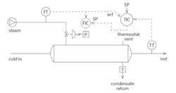
Figure 6 illustrates a cascade arrangement. A flow transmitter (FT) has been added to the steam line and a flow indicator controller (FIC) to the control strategy. The TIC has been promoted to a supervisory position and is “talking” to the TIC, not the valve. The TIC remains reverse-acting. If the header pressure changes the steam flow rate into the exchanger, the FT “immediately” reports it; and within the valve response time, the valve is moved to a position that returns the steam flow rate to the setpoint. Due to lags in the heat exchanger and temperature sensor, there probably won’t be any detectable temperature deviation.
Again, ERF is not a requirement, but if used, it must represent the TIC output value and meaning if the TIC is in charge.
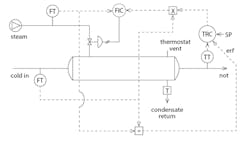
Figure 7 adds ratio to the cascade strategy. If the cold process fluid flow rate doubles, then the steam flow rate should also double. This proportionality view is the justification for a ratio strategy.
Now the output of the temperature recording controller (TRC) is a ratio value, representing the desired ratio of steam flow rate to process flow rate. As a process view, the ratio might use units of standard cubic feet per minute (SCFM)/steam per gallons per minute (gpm) of process fluid. Talking to the x-block, we might imagine the TRC saying, “Hey x-block, the desired ratio is 0.3 SCFM/gpm,” but the controller output will be a percentage. The x-block needs to perform the scaled signal calculation.
If the process inflow changes before there’s a temperature deviation without the TRC knowing about the event, the x-block will multiply the process inflow rate by the desired ratio to adjust the setpoint to the FIC.
If ERF is used, the ERF signal must represent what the TRC output would be—the same value and meaning. In this case, the actual steam to process flow rate ratio. Since all signals are likely to be in percentage of full scale, scaled signal calculations will be required.
Relative to a primitive control strategy, cascade control requires a new flow transmitter and a new controller. The cost of installation and maintenance of these devices needs to be considered when the control benefit of adding cascade is considered.
Also, the inner loop must be about five times faster than the outer loop for cascade to provide a substantial benefit.
Finally, ERF isn’t a requirement for cascade control. It’s complicated to implement, and it may only solve a brief issue after some infrequent situations. I like it, but others may weigh the performance pros and implementation cons differently, and choose not to implement it.
About the Author
R. Russell Rhinehart
Columnist
Russ Rhinehart started his career in the process industry. After 13 years and rising to engineering supervision, he transitioned to a 31-year academic career. Now “retired," he returns to coaching professionals through books, articles, short courses, and postings to his website at www.r3eda.com.

Leaders relevant to this article:

