This article was printed in CONTROL's July 2009 edition. This is the fifth part of a six-part series by Bela Liptak that describes the potential of process control for increasing safety in nuclear power plant operations. The previous four articles are
November, 2008: Nuclear Power and Cyberterrorism
January, 2009 : Nuclear Security, Part 2
March, 2009 : The Future of Nuclear Energy
May, 2009 : Three Mile Island Accident
We now know that properly designed process controls could have prevented the meltdown at Chernobyl. The causes of this accident were similar to those at 3 Mile Island seven years earlier. Both of these accidents occurred at night, after a shift change of operators who were poorly trained, uninformed and were operating the plants under manual control while their safety controls were bypassed. Ironically, the Chernobyl accident occurred during a test run, which was conducted to improve plant safety. This accident proved once more what experienced control engineers have all learned: that a process must be understood before it can be controlled.
The accident occurred while the reactor was being tested at low loading (20%) to determine the time period during which the plant would stay stable and continue to produce electricity after being shut down. The test was conducted in the middle of the night, by an inexperienced crew, while the control computer was disabled. The Chernobyl design had a positive void coefficient (VC), meaning that an increase in core temperature (more boiling) further increased power generation.
During the test on April 26, 1986, at 1:23 a.m., a runaway condition developed during which the power generation reached over 100 times the design capacity and caused a steam explosion that blew off the 2,500-ton top of the reactor. As air entered the reactor, the graphite in the core also ignited, further worsening the meltdown. As a result of the explosion and fire, 20 million curies of radioactivity was released, an amount which is 30 times the nuclear fallout that occurred at Hiroshima and Nagasaki. Thirty operators and fire fighters died and some 1,800 thyroid cancer cases (700 of them children) were reported (most of them survived). The accident also resulted in a massive relocation of the population as radiation made human life impossible over a 5,000 square-kilometer area.
Matching the Controls to the Process
I cannot possibly list all the errors in the process control system, because practically none was provided. The lack of process control can be explained partly by the fact that the plant was built for military purposes and, therefore, was designed to operate at constant loading in a plutonium-production mode. The second cause was the prevailing operating philosophy at the time in the Soviet Union, which did not trust automation and relied on operators who did not understand the process.
Examples of this lack of understanding included the use of constant controller gains on a variable gain process. The gain of this process increased (the process became more sensitive) as the load was reduced.
The operators did not understand the "inverse response" of the process either. They did not know that as the control rods are lowered into the reactor core, the reactivity does not drop immediately, but it first rises and drops only later. (Reactivity refers to the portion of nuclear energy that is available to generate steam. Reactivity is reduced—the "energy insulation effect" increased as the absorber rods are lowered. The second most effective moderator is water. Graphite is the third, and steam is the least effective moderator. Reactivity therefore increases with increased steam void formation or boiling.) In other words, they viewed a variable gain and "inverse response" process as if it was neither. Therefore, as the load dropped (reaching 7% of full loading), the VC became so large that it overwhelmed all other influences, and the meltdown of the core resulted.
As the operators did not understand the process, they attempted to control a very fast process―which at the time of the explosion had a time constant in seconds―by slow final control elements. The speed of the control rod movement was 0.4 m/s, corresponding to a stroking time of 15 seconds to18 seconds. In addition, these manual controls used a measurement with a dead time of 15 minutes, because the intermittent calculation of the operating reactivity margin (ORM), using 4,000 data points, required that much time and on top of that, the calculation was done outside the control room at a different location from where the operators worked.
The ORM is the ratio obtained if all control rods are withdrawn divided by the effect on the total reactivity of one rod. In this case, ORM should have exceed 30, and it was 7. In addition, ORM calculation was intermittent, took 15 minutes and was done 150 feet away from the control console.
If an experienced process control engineer had been on site, her or she would have known that in order to maintain stability, supply-demand matching controls were needed. This demand controller, under steady load conditions and stable conditions would have met the variations in electric power demand by modulating the thermal energy supplied by the reactor core. This electricity demand controller would have been designed as the cascade master of slave controllers that were modulating all final control elements. The slave controllers should have modulated the flow of cooling water and the position of control rods (in this case 211 boron carbide absorber rods). Naturally, these final control elements would have been selected to be faster than the process they control.
It can, therefore, be seen that, if properly designed automatic controls were used, the cascade master demand controller operating inside a safety envelope would have kept ORM above 30 and the positive void coefficient (PVC) influence within safe limits. None of these conditions were met. In addition, the test was conducted under manual control and all automatic safety systems (both the emergency protection system and the emergency core cooling system) were disabled, which is a recipe for disaster.
The Design
Design errors also contributed to the disaster. The plant had no containment building. Consequently, only the zirconium cladding and the reactor walls insulated the uranium fuel rods from the outside surroundings. On top of that, an ignitable graphite moderator was used and xenon poisoning increased as the load on the reactor was reduced.
Furthermore, the designers did not understand that once the core starts melting, the zirconium cladding will burn and thereby generate hydrogen as the oxygen in the steam is used up. In addition, they did not understand that the produced hydrogen will not only displace the cooling water (and thereby reduce heat removal), but this extremely hot hydrogen will also quickly rise, increasing the pressure in the vapor space of the reactor. At Chernobyl, as this pressure increased, it lifted the top of the reactor, and as it entered the atmosphere, it formed oxy-hydrogen, initiating a detonation.
The lessons learned at Chernobyl include that (while there is no such thing as a safe nuclear power plant) understanding process dynamics and providing redundant automatic controls to match them can minimize the probability of accidents. To maintain such safe operation, the use of manual must be minimized, and the redundant automatic safety interlocks must not be bypassed. An even more important lesson is that designing a safe control system requires the in-depth understanding of the process by experienced process control engineers, and that safety will not be improved by relying only on the advice of manufacturer’s representatives alone. The designers of Chernobyl did not realize that in designing the plant controls, process control professionals (not salesman) must play a primary role, if nuclear safety is to be improved.
The relative features of nuclear, fossil and solar-hydrogen power plants are tabulated in Table 1.
Illustration:
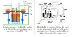
Figure 1 describes the 1000-MW Unit 4 of the Reactor Bolohoj Moshosztyl Kanalnyj (RBMK) nuclear reactor at Chernobyl, in the Ukraine.
Definitions of Terms Used:
Clading - Thin-walled metal tube that forms the outer jacket of a nuclear fuel rod
Control Rods – Absorber rods (in this case 211 boron carbide rods were used, 139 manual, 72 automatically controlled), which took 18 seconds for full insertion
ECCS – Emergency Core Cooling System
EPS – Emergency Protection System
Fuel Rods – Zirconium-clad uranium oxide having a concentration of 2% of U235
Graphite Followers – These followers were 1.25 m long and hung on the end of the control rods. When the control rod is raised, they reduce reactivity in the lower part of the core by replacing the water (positive scram effect), while at the top of the core, reactivity is increased by the lifting of the absorber. As the control rod is inserted (right side of figure above) the reactivity at the top of the core is reduced, while at the bottom it is increased as water is displaced by graphite.
ORM - Operating Reactivity Margin - The ratio: (extra reactivity obtained if all control rods are withdrawn divided by the effect on the total reactivity of one rod). In this case, ORM should have exceed 30 and it was 7. In addition, ORM calculation was intermittent, took 15 minutes and was done 150 feet away from the control console.
PDDC – Power Density Distribution Control
PVC - Positive Void Coefficient – Increased replacement of water by steam increases reactivity, which increases temperature that further increases boiling
RBMK - Reactor Bolohoj Moshosztyl Kanalnyj
RCS – Reactor Control System
Reactivity – Portion of nuclear energy that is available to generate steam.
Voiding – Proportion of steam bubbles in the cooling water
VC - Void Coefficient is a measure of the influence of voiding on reactor power generation. The Chernobyl design had a positive VC, meaning that an increase in core temperature (more boiling) increased power generation. Most (but not all!) present reactors are designed with a negative VC, so that the reactor shuts down if core temperature rises (cooling is lost).
VF - Void Fraction The portion of the coolant volume that is made up by steam bubbles. An increase in VF can either increases or decreases core reactivity, depending on the design.
Xenon burn out – Xenon poisoning occurs at low power output when Xenon135 formation inhibits the fission reaction
About the Author
Béla Lipták
Columnist and Control Consultant
Béla Lipták is an automation and safety consultant and editor of the Instrument and Automation Engineers’ Handbook (IAEH).


