Correlation flowmeters expand technology
CORRELATION flowmeters gauge fluid velocity by measuring specific parameters associated with a flowing stream at various locations in the piping. To illustrate correlations general operating principle, consider a flow stream that abruptly changes color from red to green.
The fluids color could be sensed at two points that are 1 meter apart in the piping. If the second sensor detects the green fluid 1 second after the first sensor detects the green fluid, the velocity in the pipe could be calculated to be 1 meter per second. In general, fluid velocity can be calculated when the distance between sensors is known, and the time that the fluid takes to move from one sensor to the other is measured using correlation techniques.
Note that correlation flowmeters inherently measure velocity of the flowing stream. These flowmeters generally are based on the principles of physics and physical dimensions, so no pressure or temperature compensation is needed to effect these measurements. However, compensation often is required when measuring the mass flow of a fluid.
Correlation flowmeters typically are applied to fluids in the turbulent flow regime and other fluid flows with coherent disturbances, such as slurries.
At least one correlation flowmeter has been around for about 10 years, but most were introduced in approximately the past five years. Correlation flowmeters offer some distinct advantages, not just because of their own capabilities, but also due to integrating existing flowmeter technologies with correlation techniques. In this sense, correlation flowmeters are similar to insertion flowmeters that use existing flowmeter technologies to implement insertion flow-measurement techniques.
Sonar, Ultrasonics, Optics Emerging
There are various flowmeter designs that use different measurements to determine flow rates. For example, correlation flowmeters dont disturb the fluid flow, but rather passively or actively sense its characteristics.
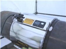
This pressure sensor array senses vortices caused by fluid velocity.
One correlation flowmeter (See Figure 1) uses a multiple-pressure sensor array attached to the outside of the pipe to measure pressure gradients caused by fluid vortices traveling down the pipe as a natural consequence of the fluid flow. These vortices are passively sensed at each pressure sensor. Computational techniques derived from sonar technology are used to determine the fluids velocity fluid. This technology also can determine the speed of sound of the fluid in the pipe, and can be installed without stopping the flow or contacting the fluid.
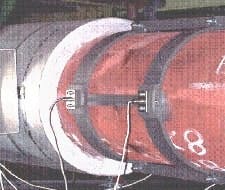
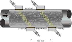
Another correlation flowmeter technology (See Figure 2 below) uses an ultrasonic transmitter/receiver pair located at a fixed distance downstream of another ultrasonic ransmitter/receiver pair. Their respective ultrasonic beams are modulated by turbulent eddies in the pipe to create a series of electronic pictures of the flow. Cross-correlation computational techniques are used to determine the velocity of the fluid. An advantage of ultrasonic technology is that clamp-on sensing methods can be used, so these flowmeters often can be installed external to the pipe without stopping the flow or coming in contact with the fluid.
Heres the sensor pair mounted on a pipe under the insulation.
Yet another correlation flowmeter (See Figure 3 below) uses an optical transmitter on one side of a pipe, duct, or stack in conjunction with a dual-optical receiver on the opposite side. Eddies in the flow stream modify optical energy in the beam path, so the first and second receivers see the same eddy at different times. Correlation techniques are used to compare received signals, and determine the streams flow velocity without compensating for temperature, pressure, humidity, or opacity. These flowmeters typically are applied to gas flows in pipes, ducts, stacks, and flares.
Dan Gysling, chief technology officer at CiDRA, says there are large-diameter, multi-phase, aggressive service applications that are prime applications for clamp-on correlation flowmeters. These applications generally involve fluids that can damage other flowmeters, such as abrasive slurries that tend to erode flowmeters, and chemically active fluids that can corrode them. However, clamp-on correlation flowmeters have no moving parts, and dont even touch the fluid, so it cant erode or corrode these flowmeter. Gysling reports seeing clamp-on, correlation flowmeters replace magnetic, Venturi, and wedge flowmeters in abrasive slurry applications, in which intrusive flowmeters often wore out after three to 24 months of service.
The multi-pressure-sensor, array-correlation flowmeter that uses sonar techniques can provide a secondary measurement of the percent of entrained gas in the liquid, which can be used to correct the liquid flow rate and density measurements, adds Gysling. For example, this technology can be used to correct net oil measurements for inaccuracies caused by incomplete separation of the gas phase prior to the flow measurement.
Mike Scelzo, process measurement marketing leader at GE Sensing says that, Correlation flowmeter technology is applicable to liquid and gas flows. Clamp-on technology is particularly effective for keeping fluids in the pipe, and for keeping impurities out of the flow stream, such as in radioactive, corrosive, toxic, sterile, and high-purity fluid applications. Theres a lot of potential for highly accurate, clamp-on correlation flowmeters that can be used to test other flowmeters and for performance testing of mechanical equipment such as pumps, adds Scelzo.
This cutaway shows the operation of the flowmeter with dual path sensors.
In addition, when certain conditions are satisfied, correlation flowmeters also can be used for in-situ flowmeter calibration. In nuclear power plants, the performance of Venturi flowmeters is verified by temporarily installing a clamp-on correlation flowmeter in series with the Venturi. The correlation flowmeter should be installed with sufficient upstream straight run, so the velocity profile doesnt affect the measurement. Gurevich adds the sensitivity of correlation flowmeters to velocity profiles is different than other flowmeter technologies because the transport velocity of the larger eddies measured are generally less sensitive to velocity profiling.
Optics Need Wide Beams
Donn Williams, vice president at Optical Scientific, reports that, Correlation technology can be implemented using non-intrusive measurement techniques to design a flowmeter that doesnt interfere with the flowing stream, and exhibits virtually no pressure drop across the flowmeter. For example, an optical correlation flowmeter can be located behind a sight glass to isolate it from the process, so it doesnt contact the fluid or interfere with the flowing stream. As a result, these flowmeters also can measure hot or corrosive gas flows without being directly exposed to the gases themselves. These flowmeters can perform daily calibration checks that meet environmental regulations in stack flow applications.
Donn warns, however, that some alignment problems can occur with optical instruments when the beam is narrow, non-diverging, and invisible to the naked eye. Ideally, optical flowmeter beams should be relatively wide compared to their receiving sensors, diverging to make the alignment more tolerant to position and vibration, and visible to the human eye to simplify alignment and maintenance.
In another application, a technician at a cement kiln has optical correlation flowmeters operating in air streams where temperatures can reach 500 F during upset conditions. In this setting, purge gas is needed to keep the flowmeter cool, even though the flowmeter doesnt contact the gas. Over time, the filters on the blowers became plugged, and affected the measurement, so purging is now implemented with flanges that allow ambient air to flow into the pipe thats under negative pressure.
Overall, the technician states, These flowmeters were easy to align, but did require some maintenance to keep the sensor clean, probably due to condensation. However, he cautions that users installing flowmeters in large-diameter pipe should pay particular attention to the velocity profile at the point of measurement. In particular, he suggests that users measure the velocity profile at various operating loads before installing the flowmeter. In addition, optical correlation flowmeters can be mounted directly across the line, while an ultrasonic flowmeter is mounted at a 45º angle. In a 12-foot diameter line in this cement application, compact installation allowed the correlation flowmeter to be mounted in the duct, while an ultrasonic flowmeter was mounted in the stack.
Ultrasonics Useful
David Peyvan, senior engineer at Entergy Pilgrim Nuclear Power Station in Plymouth, Mass., cant say enough good things about the redundant ultrasonic correlation flowmeters installed in his operation. These flowmeters are relatively simple and reliable, low maintenance, and easy to operate. Theyve operated flawlessly since they were installed about eight years ago. Peyvan adds that even small flow changes are detected in a repeatable manner by both flowmeters.
Michael Schwaebe, thermal performance engineer at Southern California Edisons San Onofre Nuclear Generating Station in San Clemente, Calif., has ultrasonic correlation flowmeters that are used for uncertainty recapture. The plant was designed for 102% operation, but could only be operated at 100% capacity due to 2% measurement uncertainties that were assumed in the design. The plants ultrasonic correlation flowmeter is used in conjunction with the feedwater Venturi flowmeter to reduce measurement uncertainty by correcting the Venturis measurement. This allows the plant to operate at a reactor power that is 1.4% higher than before the introduction of ultrasonic correlation flowmeter technology.
The accuracy of Venturi and ultrasonic correlation flowmeters can be affected by complex piping geometries that can cause flow profile distortion as far as 50 or more diameters downstream, says Schwaebe. Therefore, he cautions that the flowmeters location should be verified to make sure the flow is stable in high-accuracy applications. This stability is determined by checking whether the flow measurement is repeatable at various locations immediately upstream and downstream of the final location.
Ed Haladay, instrumentation technician at Sunbury Energy in Shamokindam, Penn., installed correlation flowmeters to replace ultrasonic flowmeters that were damaged due to high stack gas temperatures. Initially, Haladay reports, We found that the stack gas caused deposition on the glass window that etched the glass and affected the ability to measure. Maintenance became simpler when he installed an air purge that keeps the stack gas away from the glass.
All but one of Haladays correlation flowmeters performed well in operation and on relative accuracy tests. A recent inspection of the one problem installation indicated that turning-vanes at the bottom of the stack werent installed, even though they were shown on the drawings. These vanes are currently being installed to remedy a flow profile that was probably cyclonic in nature.
In conclusion, most correlation flowmeters were only developed and introduced recently. The prospects for this technology look promising because some of these flowmeters tackle flow measurements that previously werent practical, required significant effort to maintain, or were simply not possible.
| About the Author |


