Béla Lipták, PE, control consultant, is also editor of the Instrument Engineers' Handbook and is seeking new co-authors for the for coming new edition of that multi-volume work. He can be reached at [email protected].The purpose of this series is to show how the oil industry could benefit from better familiarity with automation and process control. This first article focuses on the crude oil separation process, which removes the sand, and splits the crude oil into its three phases of oil, water and gas. It discusses the control of a single separator (Figure 1), present practices and the areas where improvement is needed. Here, I show one of the separator control systems currently in use (Figure 2) and in Part 2, I will give some examples of how state-of-the-art process control could make the operation safer and more efficient.
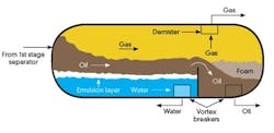
Figure 1 shows the main equipment blocks used in this process. To achieve good separation and maximize hydrocarbon recovery, it’s usually necessary to use more than one separation stage and optimize the pressure setpoints at each stage.
The separation process is an interesting one because the crude oil flow, pressure and composition all can change quickly and drastically. This in turn can affect the available residence time needed for good separation. These sudden changes not only can vary the material balance, but also can change the mist content of the gas, the thickness of the emulsion layer at the interface between the water and the oil on the inlet side of the separator, and the foam thickness on the oil outlet side.
Usually, while the first stage of separation removes the sand and some of the gas, the flowrate and composition of the remaining mixture entering the second stage still varies.
This variation makes it difficult to prevent mist carryover on the gas side, vortex formation on the liquid side and high turbulance (high velocity) that can prevent good separation between the oil and water phases and cause formation of thick emulsion (rag) layers. Even if the residence time is sufficient for good separation, a thick emulsion layer can interfere with good interface detection, and excessive foaming can cause level measurement errors on the oil end of the separator.
Present practice
Figure 1: Separation of the multiphase stream into gas, oil and water components typically relies on gravity.
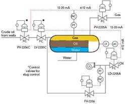
One of the worst—most wasteful and unsafe—practices that still prevails at some sites is the use of natural gas instead of instrument air in pneumatic control systems. Another, even more widely practiced characteristic of this industry is manual or semi-manual control of the process. Figure 2 shows some examples of this manual control philosophy, which results in control loop interactions that are left for the operators to handle. In addition, one can sometimes find multiple control valves used in series (LV-2205 and PV-2206 in Figure 2). Such valves can fight each other and thereby destabilize the operation.In the Figure 2 design, there is no automatic response to the variations in time constants of the process (residence time varies with load). The bypass flow controller (FIC throttling FV-2206) and the level controller (LIC throttling LD-2005A) can also fight each other (and burn up valuable pumping energy unnecessarity). This is not to say the present separation controls do not improve on the earlier, almost fully manual, control—they do. For example, using split-range control in Figure 2 is a step in the right direction.
Sensor and valve selection
For crude oil applications, control valves must be carefully selected because they can be exposed to the effects of severe flashing, outgassing and the associated erosion and vibration. Flashing (outgassing) occurs when the outlet pressure falls below the vapor pressure of the process fluid. This and the presence of fast-moving sand particles can cause erosion. One way to reduce erosion is to use multi-stage (multi-step) valves, which will split the pressure reduction into several steps, thereby more smoothly accommodating the vapor expansion.
Figure 2: The state of the art in separator control leaves room for improvement.
Courtesy of Oil and Gas Journal, Firouz Ardeshirian, Mehdi Mansuri, 9-28-1998
Measuring multiphase crude oil flows is more difficult. In older installations, individual phases of multiphase streams were either measured only after separation, or measuring total inflow was attempted using ΔP sensors (Venturi, V-cone, etc.), which aren’t suited for erosive, multiphase service, even if their pressure taps are protected from plugging by chemical seals with ceramic diaphragms. This isn’t only because their accuracy and rangeability are low, but also because the ΔP signal they generate varies with density, which is a function of the composition of the flowing mixture.
[pullquote]In more recent crude oil installations, one can find nuclear densitometers plus pressure and temperature sensors, which can help calculate the proportion of phases. Also more recently, some of the clamp-on Doppler ultrasonic and clamp-on microwave cross-correlation flowmeters have been used in applications where low accuracy is acceptable. These units, being mounted outside the pipe, are less subject to erosion damage or plugging than ΔP sensors, but on multiphase crude oil applications they usually fail because gas bubbles block the pulses.
The best option is the Coriolis flowmeter. While no single meter is capable of measuring both total flow and the composition of multiphase flows, the Coriolis flowmeter can measure both mass flow and density of the flowing mixture. Based on these two measurements (plus pressure and temperature), the composition of the mixture can be calculated. Unfortunately, it’s difficult to maintain flow-tube oscillation when more than 1-2% gas is present because the gas induces high and rapidly fluctuating damping (up to three orders of magnitude higher than for single-phase conditions), and this causes the meter to "stall" (fail).
The tasks of level measurements are less challanging. On the inlet end of the separator, the water-oil interface can be measured by magnetostrictive floats or, if one prefers, external, non-wetted sensors or nuclear gauges. More recently, instead of attempting to measure the interface as if it were at a single level, profile sensors are used. In that case, the froth layer thickness is also measured, as the multiple magnetostrictive float switches or point-sensing nuclear switches identify the contents of the separator at a fairly large number of elevation points. On the oil end of the separator, standard ΔP level measurement gives acceptable performance if the ΔP-cell is protected by extended diaphragm chemical seals on both sides.


