On these pages, in May 2010 (Maximizing Control-Loop Performance), I described two measures of economic performance for regulatory control loops based on the direction of a load disturbance:
- If the controlled variable is driven from setpoint in the "safe" direction—away from specification limits—the economic penalty varies directly with its integrated error in returning to setpoint.
- If the controlled variable is driven in the "unsafe" direction—toward the specification limit—the economic penalty varies with peak deviation, as that determines how far the setpoint must be positioned from that limit.
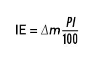
Fortunately, the integrated error (IE) is easy to calculate for any PID controller, ideal or not, as derived in that reference:
where ∆m is the percent change in manipulated variable m required to return the controlled variable to setpoint following a disturbance; P is the percent proportional band; and I is the integral time of the controller. This formula applies with or without derivative. In the presence of a sampling element of scan time ∆t, or a filter of time constant τf, or a dead-time compensator τdc, the integral time in Equation 1 is augmented thereby.
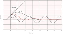
Figure 2. Even with λ as low as τ1, load regulation is unacceptable.
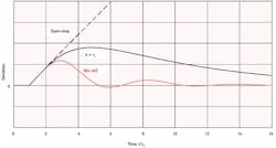
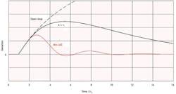
Figure 1 plots the response of an integrating process, such as liquid level with dead time, following a step-load change introduced at the controller output. The deviation grows during the process dead time just as it would in the open loop. From that point onward, the proportional action of the controller reduces its growth rate as determined by the width of the band, ideally reaching a peak before the next dead time elapses. But the wider the proportional band, the longer this takes, and the larger is the resulting peak.
Optimum Tuning
Regardless of the direction of the upset, the obvious strategy is to minimize the proportional band (maximize proportional gain), but this works only to the point where oscillation develops. Minimizing IE alone would result in continuous cycling. Damping must be provided to insure stability and allow for some variation in process parameters—a property known as "robustness." So an optimum proportional band must be found that provides the best combination of minimal peak deviation and IE, along with damping and robustness. These properties are combined in the red response curve in Figure 1, which happens to represent the minimum integrated absolute error (IAE) in response to a load step for a PI controller on this process, an integrator with dead time τd
Minimum-IAE response is a mathematical fiction that just happens to combine these desirable properties. IAE is not usually calculated on-line, as it grows with noise level and must be divided by the size of the disturbance to indicate performance. Its primary use is in simulations as in Figure 1. Then, once having accepted this as a desirable response, its pattern can be emulated while tuning on-line. The optimum response curve has a symmetrical first peak, a setpoint overshoot about one-tenth of the first peak, and a decay ratio of the damped oscillation of about 0.2. The robustness of the tuning is indicated by the approach to continuous oscillation when the proportional band is reduced by two-thirds—a change in loop gain equivalent to a 50% increase in process gain.
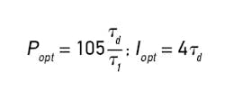
The tuning rules for attaining minimum-IAE step-load response on an integrating process with dead time are very simply:
where τd and τ1 are the dead time and integrating time of the process respectively. The proportional setting determines the symmetry of the first peak and the damping as shown; the integral setting determines the degree of overshoot or undershoot. The optimum integral time was used for all of the curves in Figure 1.
The focus here is on load response being the primary objective of a regulatory control loop. This is especially true when controlling liquid level, pressure, temperature and composition in a continuous process plant or power plant. These loops operate at a single setpoint for months at a time. Their setpoint response is therefore irrelevant. (For those loops that must respond to setpoint changes, a solution is recommended later that can be effectively applied without compromising load response.)
Model-Based Control
Over the last two decades it has become fashionable to include a process model or its inverse into the controller, resulting in such a configuration as internal-model control (IMC) and model-predictive control (MPC). Academics especially have promoted these technologies as generally superior to PID control in providing more robust and predictable response to setpoint changes and other disturbances. But this practuce results from overlooking the dynamic functions in the path of load disturbances (see Control, May 2011, "Meditating on Disturbance Dynamics." When model-based controller parameters are simply matched to process parameters, load response curves decay exponentially along the time constant in the load path. Aggressive tuning can overcome this limitation, but this practice conflicts with the intent of the model-matching procedure.
Given the huge installed base of PID controllers, it was logical to expect that some model-based proponents would develop tuning methods that could make a PID appear to emulate a model-based controller in a closed loop. This approach seems to have been encouraged by the false assumption that load disturbances enter the loop directly at the controlled variable with no dynamics in their path, as described by Chia and Lefkowitz in "Robust PID Tuning Using IMC Technology," InTech, Oct., Nov. 1992.
In practice, load variables are very much like manipulated variables, being flow rates or properties of flowing streams, like temperature and composition, and often are driven by the output of another controller. Their dynamics are similar and, in fact, usually identical to those of the manipulated variable, consisting of dead time and dominant lag. For example, in a liquid-level loop, inflow could be manipulated to balance against the outflow as load, or vice-versa.
Lambda Tuning
In recent years, this practice of emulating model-based response using PID controllers has been simplified with the introduction of "lambda" (λ) tuning, wherein λ represents the closed-loop time constant of the loop’s response to setpoint changes. Proponents suggest values for λ ranging from one to three times the dominant process lag. With λ = 1, setpoint response would be essentially the same as stepping the controller output in manual; higher values will only make it slower. When controlling flow, whose response time may be 5 seconds or thereabouts, this approach is reasonable.
But there are lambda-tuning rules for PI liquid-level controllers which make no sense at all. Liquid-level controllers are in practice never required to respond to setpoint changes, and interestingly, require no integral action to do so if required. A level controller’s output must match the load in the steady state, therefore, its output will be the same after a setpoint change as before. Then ∆m in Equation 1 is zero and, therefore, IE is also zero, resulting in an equal-area overshoot. A proportional controller can drive level to a new setpoint without overshoot, but with integral action, setpoint overshoot is unavoidable. Consequently, lambda tuning of a PI controller on an integrating process cannot achieve its intended result of exponential setpoint response.
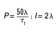
Lambda-tuning rules for an integrating process such as liquid level are given by Blevins, McMillan, Wojsznis and Brown in Advanced Control Unleashed, ISA (2003), p. 220:
where closed-loop time constant λ can be as high as 3t1. These rules give a clue to the weakness of lambda tuning: the controller settings vary directly with λ, which is chosen arbitrarily, usually as a multiple of the dominant process time constant τ1. By contrast, the minimum-IAE rules vary controller settings with dead time, which is the limiting factor in the controllability of a process.
Performance Comparison
Compare the integrated error for the two methods by solving Equation 1 for each set of rules. For lambda tuning, IE/∆m = λ2/τ1, whereas for minimum-IAE tuning, IE/∆m = 4.2τd2/τ1. To achieve equivalent performance, λ would have to be set to 2td, which for lag-dominant processes is always a fraction of τ1. If λ is, in fact, set there, then both tuning rules arrive at essentially the same results. So the real problem with lambda tuning is that λ is linked arbitrarily to the process time constant, rather than fixed at twice its dead time.
Applying the value of one time constant to lambda results in a proportional band of twice the optimum and an integral time also twice the optimum. Load responses are simulated in Figure 2 for an integrating process whose time constant is five dead times.
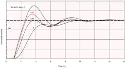
Figure 3. Again, with λ as low as τ1, load regulation is unacceptable.
With the proportional band and integral time both doubled under lambda tuning, IE is now four times the optimum, and peak deviation is higher by a factor of 1.58 and takes more than twice as long to be reached. Since IE increases with λ2, investigating higher values is pointless.
Self-Regulating Processes
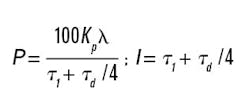
Lambda-tuning rules for self-regulating processes are given by Blevins, et. al., as:
where Kp is the steady-state process gain. IE/∆m then comes out to be Kpλ. Again, observe the arbitrary setting of the proportional band as a function of λ, which could be anywhere from 1τ1 to 3τ1. By comparison, the minimum-IAE settings for a lag-dominant process are similar to those given in Equation 2, except that the coefficient for the integral time reduces from 4 to 3.4 to 2.9 as the τd/τ1 ratio increases from 0 to 0.1 to 0.2. This covers the bulk of fluid processes such as heat exchangers, columns and stirred tanks.
Like this article? Sign up for the twice weekly Control Update newsletter and get articles like this delivered right to your inbox.
Consider a self-regulating process where τd/τ1 = 0.2. Minimum-IAE tuning gives Popt = 105Kptd/τ1 and Iopt = 2.9τd, with a resulting IE/∆m = 3.05Kptd2. To approach this result with lambda tuning, λ would have to be reduced to 0.12τ1, or 0.6τd. However, Equation 4 does not allow an integral time less than τ1, so minimum-IAE results cannot be approached. Figure 3 compares the load response for the case where λ= τ1
Determining setpoint
Figure 4. Setpoint is determined by its gain setting.
Continue Reading

Leaders relevant to this article:

