Q: I happened to read your article, “Rangeability of equal-percentage control valves” (Sept. 2013, p. 102). It was informative and crystal clear as to what rangeability for =% control valves means. This is the first time my mind was getting clear on this subject as I was reading sentence by sentence. Thanks so much, but I also need some of the same information for linear control valves.
I’m using a pressure-independent balancing and control valve (PIBCV), flow range 180 l/h to 1,300 l/h, with a proportional actuator. It’s a linear control valve. Valve authority is 100% and DP across these valves is constant. Please let me have more information about the rangeability of these PIBCVs and also comment on the maximum rangeability I can expect. Is 1:300 possible by any chance, or is even 1:50 possible or not? I appreciate your response.
Milind Pawar / [email protected]
----------
A: Before talking about your PIBCV, I will discuss control valve rangeability and characteristics in general. (This topic is covered in more detail in Volume 2, Chapter 4.13 of my handbook.)
If in a particular control loop our goal is to obtain quarter-amplitude damping, stable control will be obtained if the loop gain (Gloop = controller output/measurement input) is about 0.5. The loop gain equals the product of the gains of the loop components. (Gloop = Gprocess x Gsensor x Gcontroller x Gvalve). Naturally, to obtain this loop gain on a fast (high gain) process, the controller must be tuned for low gain (wide proportional band) and inversely, for a slow processes, the controller gain has to be high.
One should use a linear control valve when all the other loop components, including that of the process, are more or less linear. Note that a device or a process is linear if their gains (% input/% output) are constant throughout their ranges. For example, a control valve is linear if its gain is constant within its stroke range set by its rangeability (Gvalve = maximum flow/100% stroke = constant). Determining the best valve characteristics for a particular application can require complex dynamic analysis, but for most common applications, my rules of thumb are listed in Table I.
[sidebar id =1]
Valve rangeability is the ratio of maximum to minimum controllable flow. The term “controllable” is a matter of definition. I like to limit the valve operation to a flow range inside which the valve gain remains within ±25% of its theoretical gain. Figure 1 illustrates the rangeabilities of both a linear and an =% valve. The dotted line #3 assumes the theoretical gain of a particular linear valve as 1.0, while the solid line #4 shows the actual gain of that linear valve. According to my definition, the rangeability of that valve is the ratio of maximum to minimum flows within the flow range, where the actual valve gain is within ±25% of the theoretical. In this case, it is about 60%/3% = 20:1.
[sidebar id =2]
Now, as to the rangeability of the PIBCV valve of AB that you asked about. This valve is a 3/4-in., flow-limiting valve used in HVAC applications to balance water distribution among many radiators. While the supplier calls this valve linear, its full stroke lift is only 0.2 in., so while it can be linear within that distance, the design is bordering on quick opening. This valve is good for providing a limit of maximum flow within an adjustable range of 5:1, but I would not use it for closed loop control, only for flow limiting.
For the 50:1 or 300:1 rangeabilities you mentioned, you need at least two linear valves in parallel, a larger and a smaller one. In high-quality linear valves, you can obtain a rangeability of 20:1 in each.
Béla Lipták / [email protected]
----------
A: You can find the mathematical derivation of the installed flow characteristics of a control valve in Carlos Smith and Armando Corripio’s Principles and Practices of Automatic Process Control, 1st edition, John Wiley & Sons, N.Y., 1985, pages 147-152.
I have my own derivations of the same, following the method used by Smith and Corrpio. I obtained the same graphs as the ones published in Smith and Corripio, albeit I used Matlab software. If you would like me to send you this material, you can contact me.
I’ve read that “rangeability goes up to infinity” as published by a major control valve manufacturer. These needle-type valves were put in water spray service in a desuperheater, attemperation application. They all failed. The stems had to be replaced at every shutdown during 2000-09, when I was a control valve specification holder. I hope these help. Thanks for your interest.
Gerald Liu, P. Eng. / [email protected]
----------
A: My ISA book (Wade, H.L., Basic and Advanced Regulatory Control, System Design and Application, 2nd edition—3rd edition available soon) describes two possible ways to increase valve rangeability:
- Install a small valve and a large valve to operate in parallel; or
- Install a small valve and a large valve to operate in sequence.
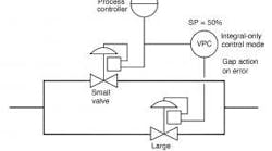
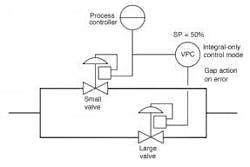
Small and large valves operating in parallel (Figure 2) depicts a valve configuration in which a small valve and a large valve are used in parallel. The small valve is used for moment-to-moment control of the process. The large valve is operated by a valve position controller (VPC). Its measurement is the process controller’s output. Or better yet, if a stem position transmitter is available on the small valve, then its output can be the measurement of the VPC. The valve position controller attempts to keep the small valve within its operating range by increasing or decreasing the large valve’s position whenever the small valve approaches the upper or lower limits of its range. The valve position controller is an integral-only controller with a setpoint of 50%. It’s recommended that the control algorithm should have a gap centered on either side of 50% and within that gap, the effective error is to be zero.
Figure 2: Parallel valve operation for increased rangeability.
Reasonable limits for the gap are 20% and 80%. In this control system, the output signal of the process controller always moves the stem position of the small valve back to within its range limits. This allows the large valve to remain in its new position until the small valve position reaches one of the limits of its gap.
The purpose of the gap is to permit the small valve to have a reasonably wide range of travel without causing a “hunting” movement of the large valve.
Small and large valves operating in sequence: If the process turndown requirements necessitate use of an equal-percentage valve characteristic (see Chapter 3 and Appendix A) with wider rangeability than can be provided by a standard control valve, then two equal-percentage valves, one large and the other small, can be installed in parallel but operated in sequence. The Cv’s of the valves should overlap, and pressure switches or other logic devices are provided to make sure that only one of the valves will be open. Then the required Cv is within the overlap range.
Also see Shinskey, F.G., Process Control Systems, Application, Design and Tuning, 4th edition, pages 61-64 for more detail on this approach.
Harold Wade / [email protected]
----------
A: This is a great question and one that I’ve considered for years. The issue of valve rangeability is often misunderstood and ignored. No valve is perfect. Every valve has some friction involved in moving the stem and thus some uncertainty of position and flow.
You’ll need to consider just how you want to define rangeability. It’s not as simple as it might seem. Typically, it’s defined as maximum flow/minimum controllable flow. You can expect a control valve to affect flow even at very small opening, but the problem is that, since the uncertainty of valve stem position in mm is more or less constant over the stroke range, this becomes a large portion of the stem position at low flows. This uncertainty of, say, 1 mm of stroke is a much larger percent at low flows than that same difference when the valve is nearly full open.
If you have access to the ISA standards, please look at ISA 75.25.01 and 75.25.02. The first defines all the terms and demonstrates how they work, and the second provides the background.
The short answer is that all valves I ever saw suffered the problem that there is some small change in input signal that doesn’t cause the valve to move at all. That small change might not be identical for an increase in signal as for a decrease in signal. In other words, a valve is likely to have a “memory effect” in that the state of the packing is not the same after a move up as it is moving down. There also are differences between a slow rate of change in signal and a faster rate of change in signal.
In real life:
- A more powerful actuator is likely to position the valve more accurately.
- Some packing materials have less friction, and thus allow better accuracy of positioning. If you don’t really need high-temperature packing, don’t use it. Graphite packings normally have much greater friction than most others.
- An eager operator with a wrench can tighten a control valve packing gland enough to prevent any motion and any control. It can be valuable to check valve action if control problems exist.
- All control loops with reset action will cycle their control valves. You can’t escape that. You can’t tune the controller to eliminate that. You can slow the reset and slow the reset cycle. You can reduce the proportional gain and hide the cycling. It will not go away, but it can be reduced with a better actuator/positioner and low-friction packing.
I once did an ISA paper describing how to analyze the required control loop performance to estimate the control valve performance that has to be specified. One of the conclusions was the requirement to consider how fast the process can change and also how accurately the flow needs to be controlled. Keep in mind that control can’t be perfect; never accept the demand for it.
Cullen Langford / [email protected]
This column is moderated by Béla Lipták, automation and safety consultant, who is also the editor of the Instrument and Automation Engineers’ Handbook (IAEH). If you have an automation related question send them to [email protected].

Leaders relevant to this article:


