See more Control Talk articles.
Stan: I've been an instrument engineer all of my professional life, and Greg spent the first eight years of his career in construction, installing, checking out and commissioning instrumentation (between stints as the lead engineer in instrumentation design in new plants).
Greg: I moved on into engineering technology doing modeling and control for the rest of my 33 year career as a user. I always took a great interest and appreciation in getting the best measurements and control valves. In fact, my early specialties of compressor, furnace pressure and pH control, the resolution and response times of the sensors and control valves were critical, and could make or break the system. I was given the time and freedom to develop the knowledge needed and the encouragement to publish as much as possible of what I've learned. Robert Armstrong, who I met at a recent users group meeting, had an even longer heritage in instrumentation by virtue of his father and himself each having more than 30 years of experience in instrumentation system design. I can only imagine the fun and benefit of being able to discuss your field experience with your Dad. Instrumentation is an exciting profession. I fell into the profession by accident. It's difficult to explain to others, as can be seen in the cartoon on the front cover of my and Stan's first funny book, How to Become an Instrument Engineer—the Making of a Prima Donna. In the cartoon, a partygoer like me with drink in hand asks, "Just what does an instrument engineer do?" By the way, please ask Susan Colwell, ISA manager of publications, to put this book back in print. When ISA went to the digital-only version, sales dropped to zero.
Stan: We would recommend the career to anyone. Very few until recently have moved out by choice once having entered the profession. We just need to make sure it's still a viable option by showing the significance and value of what we have to offer. Robert had a good idea of the potential career in instrumentation from his Dad. Here we tap into Robert's knowledge on how to improve the reliability and linearity of control valves. One of my areas of expertise was valve design and selection, so combined with Greg's sensitivity to valve sensitivity, we have a great basis for helping our readers get the most out of control valves. We start out with getting a perspective of the effort invested.
Greg: I was impressed by Robert's detailed analysis of how to identify and use the installed characteristic that included considerable knowledge about fluid flow and the piping system installation details as seen in Robert's presentation, "How to Select the Right Control Valve." Robert, what was your starting point?
Robert: I used Bernoulli's Theorem and the Darcy formula as documented in the Crane Technical Paper No. 410, "Flow of Fluids through Valves, Fittings, and Pipe." The paper is an excellent, extensive resource with correlations, formulas, figures, tables and examples.The equations were set up in Mathcad because it has a powerful solver and graphing capabilities, displays all equations in conventional math notation—no hidden cells or formulas—and it can readily handle automatic conversions between U.S. Customary and SI engineering units. The Mathcad equations and input data for flow resistance of the piping segments were based on the piping isometric.For the segment with the control valve, the flow resistance was also a function of the control valve flow coefficient (Cv) whose values as function of position were determined from the vendor's control valve sizing catalog. Sizing catalog tables rather than theoretical curves (e.g., equal percentage) must be used for the inherent flow characteristic curves because the deviation between the theoretical curves and actual curves is significant. The installed flow characteristic is derived from the inherent flow characteristic and the varying pressure drop available to the control valve as function of flow based on the system resistance and pump curve. For the segment with an orifice plate, the flow resistance was also a function of beta ratio. The pump curve also needed to be entered.
The first application consisted of two pumps on a vessel with a recirculation line back to the vessel with a control valve and restriction orifice. There was a flow measurement in the total feed to the users downstream. Initially, this flow measurement was used for a total flow controller that throttled the control valve in the recirculation line. However, operations didn't realize that the total flow was already controlled by each feed having its own flow controller. The total flow controller had to be put in manual to stop the oscillations from the fighting loops. The cavitation in the recirculation control valve was also severe. The recycle valve position needed to be intelligently positioned to minimize cavitation and enable tight individual feed flow control.
The Mathcad model provided a three-dimensional (3D) plot of valve pressure drop versus recycle line orifice beta ratio and control valve position. The plane for critical pressure drop was added. A valve pressure drop above this critical plane would correspond to valve cavitation. The 3D plot enabled visualization of the best beta ratio in terms of preventing cavitation and enabling a lower minimum valve position that will ensure there is enough forward flow based on the pump curve for the highest combination of feed flow requirements.
Once the best beta ratio is selected, I could compute the flow and the process gain (change in flow per change in valve signal) as a function of valve position. The resulting process gain showed that the equal-percentage type of inherent characteristic introduced excessive nonlinearity. This was fundamentally the wrong choice of flow characteristic, which would have been a problem if we were trying to do closed-loop control, say for example pump discharge pressure control. For this application, it was sufficient to use the ability gained from Mathcad model to compute the recycle flow providing a look-up table to set the recycle valve position needed to ensure meeting the total feed flow requirement. The solution greatly prolonged the life of the control valve, significantly reducing maintenance costs and improving onstream time by greater reliability.
Stan: We've known for a long time that control valve installed characteristic is a curve rather than a straight line, introducing a significant nonlinearity into the control loop.
Greg: The slope of the curve is the valve gain that when multiplied by the process gain and measurement gain becomes the dimensionless open-loop gain seen by the controller, where the PID gain is inversely proportional to the open-loop gain. The measurement gain is simply 100% divided by the measurement span in engineering units, which is constant. The process gain for a flow loop is 1, making the open-loop gain simply the valve gain (e.g., gpm / %) multiplied by the measurement gain (e.g., % / gpm). Thus, for flow loops, the control valve is the total source of nonlinearity. For evaluating the linearity of control valve characteristics, the Y axis of the installed flow characteristic is % flow and the X axis is % valve position, resulting in a dimensionless valve gain (% flow / % stroke) that is often called a process gain. EnTech developed a specification that the process gain (i.e., valve gain) should be within 0.5 and 2.0 (4:1 gain change) in the operating range of the control valve. I have espoused this guideline in my books, most notably Essentials of Modern Measurements and Final Elements in the Process Industry.
Stan: Split-range control valves add a complication that is often not addressed. Robert, what is an example of how you have improved split-range control?
Robert: I had a fuel gas application where the pressure controller was manipulating split-range fuel gas control valves where the valves had different capacities and flow characteristics. In this case, the installed flow characteristic was pretty much the inherent flow characteristic because the pressure drop across the valves was relatively constant. I was consequently able to use the Cv table from the valve sizing catalog to develop a polynomial that would provide a plot of valve flow versus position. The slope that is the valve gain could also be computed. Since the small valve had less capacity and its flow characteristic flattened out above 70%, there was a sharp discontinuity seen as a sharp drop in valve gain at the conventional split-range point of 50% PID output. Just looking at the combined flow characteristic, a high output limit of 80% stroke for the small valve and a split-range point of 40% would be better. Upon further analysis of valve gains, a high output limit of 70% stroke and split-range point of 30% offered better linearity, enabling the valve gain to stay within the 0.5 to 2.0 (% flow / % stroke) guideline for the expected throttle range. The improved linearity of the split-range control valves enabled a smooth startup and subsequent years of great satisfaction with the project.
Stan: Eliminating a potential problem can help you gain appreciation for all of the other things that were done right on a project. Thus, the benefits extend beyond the focus of the solution. The reverse is more obvious where an unsolved problem can spoil the satisfaction and perception of the project despite all of the great things that were done.
Greg: The linearization of the control valve flow response helps reduce the oscillations that often occur at the split-range point due to the discontinuity. In split-range applications where the valves are throttling counteracting streams (e.g., coolant flow vs steam flow, acid flow vs base flow, nitrogen flow vs vent flow), going back and forth across the split-range point causes larger oscillations and wastes raw materials or energy. By linearizing the flow response as much as possible, an auto tuner and adaptive controller are freed up to focus on the process nonlinearity introduced by throttling the different streams. Directional move suppression can reduce crossings from unnecessary movement toward split-range point by a setpoint limit in this direction on the analog output block in concert with external reset feedback in the PID controller.
Stan: Here we have seen the value of investment in modeling and analysis. Greg and I have a sense that this expertise—and even the recognition of its value—is disappearing.
Robert: Even though the initial investment of making such analysis of installed flow characteristics, which require just a couple of hours of effort once you have the details, continues to yield benefits, I don't see this type of analysis being done. In general, the time and interest no longer exists. Maybe 20% of new engineers are technically oriented and want to know why and how to do better, but the others often look at the instrumentation and process control profession as just a stepping stone to management. It is a self-fulfilling prophecy where the managers today don't have extensive experience in the profession and don't understand much beyond immediate cost of a solution or project. I am personally making the effort to mentor an aspiring, talented young engineer, Sumiti Lamichhane, who understands the significance of the knowledge to be gained. Sumiti is one of the new members of the ISA Mentor Program.
Greg: The protégées/protégés and resources in the ISA Mentor Program and the MYNAH mentor program I have developed understand the value of improving process control. These people are examples of our best hope for the future. We are seeking to start a movement to change the widespread and increasing perception that cost rules. The price of an instrument or control valve and the time spent in design are presently the focus because they are obvious. The benefit of a better design or installation is not considered if knowledge is cursory. Manufacturers respond to this, and offer instruments and valves with lower price tags touting simpler installations. I sat in a presentation by a supplier who was touting the use of a simple mechanical level switch instead of radar because it was cheap and simple to install. He did not understand the benefit of throttling control instead of on-off control in terms of upsetting other loops affected by the extreme cycling of the flow, or the precision radar offered for material balance control and residence time control. Trying to show a performance advantage seems to have taken a back seat. This is most prolifically seen on packaged equipment because plant standards may not be updated or enforced. I think we need to develop several case histories that dramatically show the consequences. This is being done in the ISA War Story series, the ISA Mentor Program Web Seminar series, and my March Control magazine feature article, "Control Valve Response—Truth or Consequences." If you have some case histories you would like to share, please send them to my MYNAH email address. Meanwhile, check out my Control Talk Blogs "Unexpected Benefits of Signal Characterizers" (Oct. 20, 2015) to see how knowing the installed flow characteristic can pay off in terms of linearization and "Best Control Valve Flow Characteristic Tips" (May 6, 2015) on how the application largely determines what type of trim is best.
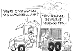
"Top 10 Things You Don't Want to Hear from Your Valve Supplier"
10. I went out for bids and found the cheapest possible valves.
9. These valves have been extensively used in packaged equipment.
8. These valves have such a tight seal, I dare you to try and open them.
7. You can standardize on these valves for isolation and sequences.
6. You get all the flow you need when the valve is just 10% open.
5. Why do you want to know the valve response time? We have quick opening trim.
4. Thanks to my1969 Guidelines based on Nyquist Plots, I was able to omit positioners.
3. We don't need to know the piping system.
2. All I need is the available pressure drop at the design flow.
1. What do you mean by installed flow characteristic?
