This column is moderated by Béla Lipták, automation and safety consultant and editor of the Instrument and Automation Engineers’ Handbook (IAEH). If you have an automation-related question for this column, write to [email protected].
Q: What is the official definition of valve gain? When I want to calculate the gain of a valve, is it necessary to normalize the change in flow with respect to the rated flow? Which of the following equation defines the valve’s gain: ((ΔQ)/ (rated Q)) / (Δvalve travel in %) or (ΔQ) / (Δvalve travel in %)?
Ali rahimi
[email protected]
A: The valve gain is a variable, except in case of linear valves. At any particular point, the gain of any device is the change in its output divided by its input (%Δo/%Δi). So for a control valve, at any particular opening, the "inherent" valve gain is the ratio of its change in its flow (%ΔF) or valve coefficient (%ΔCv), divided by the change in the input that caused it. This input change is the change in the valve travel/ lift/stroke (%Δstroke) that is caused by the change in the control signal (%Δm). Therefore, the gain resulting from the inherent valve characteristic of the valve is:
Gi = (%ΔCv) / (%Δstroke)
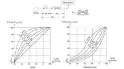
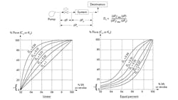
Figure 1: As the distortion coefficient (Dc) drops, the valve characteristic shifts. The shift of linear valves is toward quick opening and for equal percentage (=%) valves is toward linear.
*Note that the minimum "controllable" flow increases as DC drops.
If we are interested in accurately determining the gain in terms of flow (Gf), we must also consider the actuator’s linearity (if the valve has no positioner) and any change in valve pressure drop (ΔP) either because of the pump curve or because when we use constant-speed pumps, the valve ΔPv rises as the flow drops. In addition, ΔPv can also vary, because of flashing, cavitation, choking, etc. So the gain at different flows (Gf) can be substantially different from the "installed" valve gain:
Gf = (%ΔF) / (%Δm)
Figure 1 illustrates the distortion in valve characteristics caused by the change in the valve ΔPv as the flow changes. At low flows, the valve drop (ΔPv) is a larger portion of the total pressure drop (ΔPt) than at high flows, when the system drop (ΔPs) rises and (ΔPt) drops.
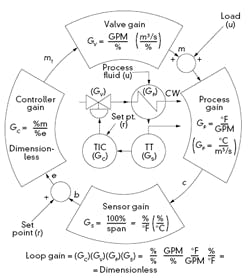
One might also note that the stability of a control loop is not only a function of the valve gain but is a function of the product of all loop components, as illustrated in Figure 2. Therefore, it is not enough to have accurate knowledge of the valve gain (Gv) at a particular load, but also of all other loop components, such as that of the process (Gp), of the sensor (Gs), etc. This means that when we "tune" a controller, the task is to adjust the controller gain (Gc), until the gain product of all the loop components is about 0.5. If we tune the loop at normal load, when the load changes, this gain product will also change and the loop can become sluggish or unstable. Naturally, in our digital age, it would be feasible to provide the controller with automatic retuning capability, so that as the load changes, it would automatically return the gain product to near 0.5, but that is seldom done. If you want to read a detailed discussion of stabilizing control loops while loop gain changes with load, see my handbook.
Béla Lipták
[email protected]
Figure 2: Ideally, auto-tuning could automatically adjust the controller gain (Gc), so that the loop gain (the product of Gc, Gv, Gp and Gs) would remain near 0.5 at all loads.
A: As defined in the Emerson Control Valve Handbook, gain is an all-purpose term that can be used in many situations. In its most general sense, gain is the ratio of the magnitude of the output change of a given system or device to the magnitude of the input change that caused the output change. Gain has two components: static gain and dynamic gain. Static gain is the gain relationship between the input and output and is an indicator of the ease with which the input can initiate a change in the output when the system or device is in a steady-state condition.
Sensitivity is sometimes used to mean static gain. Dynamic gain is the gain relationship between the input and output when the system is in a state of movement or flux. Dynamic gain is a function of frequency or rate of change of the input.
Inherent Valve Gain is the magnitude ratio of the change in flow through the valve to the change in valve travel under conditions of constant pressure drop. Inherent valve gain is an inherent function of the valve design and a function of valve travel: inherent valve gain = (change in flow)/(change in travel) = slope of the inherent characteristic curve. Many valve designs, particularly rotary ball valves, butterfly valves, and eccentric plug valves, have inherent characteristics that cannot be easily changed; however, most globe valves have a selection of valve cages or plugs that can be interchanged to modify the inherent flow characteristic.
Installed Valve Gain is the magnitude ratio of the change in flow through the valve to the change in valve travel under actual process conditions. Installed valve gain is the valve gain relationship that occurs when the valve is installed in a specific system and the pressure drop is allowed to change naturally according to the dictates of the overall system. The installed valve gain is equal to the slope of the installed characteristic curve, and is a function of valve travel.
Francisco Alcalá
[email protected]
A: I would suggest downloading and reading the free Emerson Control Valve Handbook, 4th edition. This is an industry standard reference. It defines "gain," "inherent valve gain," "installed valve gain," "loop gain," and "process gain."
Paul Gruhn
[email protected]
A: In dynamics, a gain is the change in output divided by the change in input. A valve gain is the change in flow in engineering units divided by the change in % signal, which is the slope of the installed flow characteristic that takes into account the effect of the ratio of the valve pressure drop to total system pressure drop. If this ratio is very small in an attempt to increase energy efficiency, the installed flow characteristic for a linear inherent characteristic will approach a quick-opening inherent character that has an undesirable steep slope (high valve gain and excess sensitivity) at lower positions and a flat slope (low valve gain and insufficient sensitivity) at higher valve positions. Note that excess sensitivity increases the amplitude in flow of the limit cycle from a given stick-slip in %. A low sensitivity causes a wandering of the PID output. Changes in sensitivity change the maximum allowable PID gain (everything else being equal).
Since the PID algorithm works with % signals, the open-loop gain seen by the PID is Δ% PID PV / Δ% PID output and is thus dimensionless for self-regulating processes. For integrating processes, the process gain does not cancel out the time units in the valve gain and you end up with an open loop gain with units of % / sec / %, or simply 1/sec. The open loop gain is the product of the valve gain, process gain and measurement gain. For a linear measurement, the measurement gain is simply 100%/PV span. For composition, temperature, and pH the process gain is best identified as the slope on a plot of the process variable versus the ratio of the manipulated flow to feed flow. The process gain is the ΔPV / Δ ratio, and ends up being inversely proportional to the feed flow.
Technically, an inherent equal percentage characteristic has a slope and valve gain that is proportional to flow that would help cancel out the process gain that is inversely proportional to flow. However, the gain compensation changes with the installed characteristic, sizing of the valve, and changes in the ratio due to changes in operating conditions and equipment conditions.
Greg K. McMillan
[email protected]
