This column is moderated by Béla Lipták, automation and safety consultant, who is also the editor of the Instrument and Automation Engineers' Handbook (IAEH). If you have an automation-related question for this column, write to [email protected].
Q: I am an engineer working in operation and maintenance of test facilities in the Indian Space Research Organization. I have a requirement for a new control valve to be installed in our facilities. Per ISA guidelines, I have calculated the max and min Cv required by the process conditions. I am selecting equal percentage characteristics for the control valve, but I need to specify the rangeability for the control valve.
For this, I have calculated the ratio of required max Cv to min Cv (10 for the particular case), and I have selected the valve rangeability (50:1), which is higher than this ratio. Kindly correct me if my method is wrong. I would be highly obliged if you can guide me on this point.
Jai Vishnu K.S
[email protected]
Figure 1: Equal percentage valves are used to provide stable control on heat transfer loops by compensating for the process gain that drops with load by its increasing their gain, so that the loop gain stays constant at around 0.5.
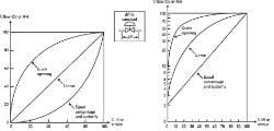
Figure 2: At constant ΔP, the Cv of an =% valve increases by a fixed percentage of the prevailing Cv whenever the control signal (valve stroke) opens by 1%. On a logarithmic scale, the characteristics of an =% valve is a straight line. The slope of that valve is the =% value.
A: I could just say that your vendor is making a false claim (50:1) and your valve is probably OK, but I want to be more helpful, so I will give a brief explanation of what equal percentage (=%) is, why we use it (Figure 1), what its gain is, and how that gain relates to stable control.
If a 1% change in the control signal results in a 2% change in the flow (also called load) through that valve, it has a gain of 2. So long as the pressure drop accross the valve (ΔP) is constant, the terms % flow, % load and % valve coefficient (Cv) are interchangeable. The gain of linear valves is constant; the gain of non-linear valves (=%, quick opening, parabolic, hyperbolic, etc.) varies with load. The gain of an =% valve rises with flow, so a 1% control signal change will cause a 3% change in the flow if the =% value of the valve is 35. The left side of Figure 2 shows the relationship between percentage of valve stroke and percentage of flow (Cv) of three valve characteristics on a linear scale, while the right side shows the same on a logarithmic scale.
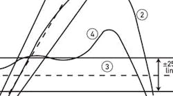
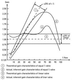
With this long introduction, now we can talk about rangeability, which (at constant ΔP) is the ratio of that Cvmax/Cvmin at which the valve maintains its =% characteristics within 25%. Because the manufacturing tolerance of the plug is about 10% to start with, and typical instability is about 5%, the valve should not be used near the two ends (0% and 100% stroke). Figure 3 shows one recommendation, suggesting that the theoretical (line 1, dotted) and the actual installed (line 2, solid) gain-to-load relationship of an =% valve should be within 25%. We can see that the actual (solid) line stays within 25% of the theoretical (dotted) between about 5% to 70% of the flow (Cv). Therefore, the valve rangeability is 14:1. So, as far as your question is concerned, an =% valve for your application is OK. Size it so that your Cvmin to Cvmax range will fall inside the 5% to 70% range. As to the vendor's claim of 50:1, forget that. By the way, if the ΔP across the valve changes with flow (pumping systems), or if you have flashing, cavitation or sonic velocity (choked flow) conditions, you need an intelligent positioner. See Chapter 6.7 in Volume 2 of my Instrument Engineer's Handbook.
Béla Lipták
[email protected]
A: For a detailed understanding, please follow as Béla has suggested. Please find basic rules for selecting control valve on rangeability aspect. From process flow minimum and maximum ratio perspective, no control valve can handle a rangeability of more than 1:20. There could be specially manufactured characteristic trim which can improve rangeability further.
Figure 3: The actual (installed) characteristics of an =% valve stays within 25% of the theoretcal between about 5% and 70% Cv (flow), according to Les Driskell.
When a process requires a rangeability of 1:50, you need also be careful to select the right flowmeter because no single flowmeter element, except an ultrasonic meter, can give you such high rangeability.
From a control valve sizing perspective, you need to satisfy the requirements of controllability. At min and max flow, generally 10% and 70% opening should be achieved to have good controllability.
When one control valve does not meet your flow rangeability requirement, two control valves or more should be considered in parallel. To achieve high rangeability you can use two different trims in the same body. First trim can serve minimum to normal flow range; the second one can be used when the flow is normal to max. Or this ratio can be adjusted according to the available standard trim ranges.
D Guha
[email protected]
