Q: For split-range control valve applications (valves in parallel, where one is used for low-flow and the other, bigger valve is used for high flow), what’s the correct way to assign flow rate and differential pressure to each valve? Should the differential pressure be the same for both valves in any flow? Also, how should we correctly assign the split point? Should we use split range at all?
Mohd Zhafran A. Hamid, PE, I&C Specialist, Petronas / [email protected]
A1: I suggest using a valve-sizing program that accounts for the piping system design, pump curve and operating conditions to not only size the valves, but also see how the pressure drops change and how installed flow characteristics change with flow and operating conditions. I suggest using globe valves with low-friction packing, diaphragm actuators and smart positioners tuned for high-proportional gain with no integral action to minimize lost motion (backlash) and stiction.
I also suggest using signal characterization to linearize the response based on knowledge of the installed flow characteristic. Using precise valves with linearization of flow characteristics should help reduce the oscillations often seen due to changes in process gain, lost motion and stiction at the split-range point as the big valve tries to open. If linearized properly, a remaining change in process gain can be addressed by setting the split-range point equal to the small valve’s flow capacity as a percent of the total flow capacity of both valves. The small flow valve capacity is often chosen to be about 20% of total flow capacity, but it can be more intelligently set based on operating conditions.
Since the objective is to obtain greater precision (less lost motion and stiction), the adjustments of the total flow should be done by throttling the smaller valve most of the time. This can be done by using valve position control (VPC) that detects the opening of the small valve, while its setpoint is adjusted in a cascade manner by the process controller, and its output throttles the large valve. Assuming good linearization by signal characterization and having a VPC with a setpoint of 50%, the small valve will throttle most of the time.
The VPC tuning must prevent any fighting with the process controller and must not allow the small valve to end up at its output limits (fully opened or closed). The VPC should have integral-only control, adaptive control and external reset feedback. Enabling rate limits can help meet goals for positioning the large valve. I suggest feedforward or ratio control, if possible, to proactively position both valves for load disturbances and setpoint changes.
Greg McMillan, former senior principal software engineer in simulation, Emerson / [email protected]
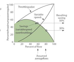
A2: If the load is mostly friction (total head divided by static head ˃2), variable speed pumping is justified because you’re saving pumping energy (Figure 1).
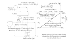
I assume you’re using two valves because throttling a single variable speed pump or one control valve on the discharge of a constant-speed pump wouldn’t provide enough rangeability. If your rangeability requirement exceeds 25:1, you can obtain that by either sequencing two valves using smart, relay-type, high-gain positioners with no integral action (Figure 2), or by controlling the position of the smaller valve.
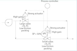
VPC can provide fast and accurate control, but it has a disadvantage because the valves have packing friction, which must be overcome before they move (jump). Strong positioners and low packing friction can minimize the effect (Figure 3).
Bela Liptak / [email protected]
A3: Valves are installed in parallel to improve control accuracy for larger flows by taking advantage of a smaller valve, and expanding the control range of flows beyond the control accuracy of the large valve. To do this, we used a VPC. The process controller throttles the small valve and a VPC on the small valve—with a fixed setpoint of 50% open—and moves the large valve to drive the small valve towards 50%. The small valve makes small changes in flow, while the large valve moves to keep the small valve inside its throttling range. This scheme is used for difficult pH control, where the process has a very high gain near the control point, while the required flow varies widely.
With this configuration, the dynamic response is poor and control has problems. This is because the valves don’t move smoothly but in steps because, before it moves, the valve actuator force must overcome the static friction, and at that point, it jumps. Smaller valves make smaller jumps. The jump steps create a permanent cycle in flow. Jumps can be reduced by lowering the stem-packing friction, using larger actuators, stronger valve positioners, and reduced free motion in the mechanical linkages and connections.
Cullen Langford, control consultant / [email protected]
A4: One simple, yet effective solution is to have a common controller for both valves, and one valve calibrated from 0% to 50% fully open, and another at 50% to 100% fully open on this controller output.
You could design other ways, too. You may aim for two parallel valves for various reasons, such as avoiding one huge valve size or two types of operating conditions. One best practice for valve sizing is ensuring that the valve is generally open between 30% to 70%.
Dr. H. S. Gambhir, control consultant / [email protected]
