This column is moderated by Béla Lipták, automation and safety consultant and editor of the Instrument and Automation Engineers' Handbook (IAEH). If you have an automation-related question for this column, write to [email protected].
Q: Dear sir, what guidance is available for calculating the relationship between flow profile and flowmeter accuracy?
Rajesj Shukla
Instrument Engineer
[email protected]
A1: When sizing a flowmeter that's sensitive to flow velocity profile variations, a measurement error will occur if that profile changes from that used when sizing the device. Naturally, there are flowmeters (magnetic, Coriolis, etc.) that are unaffected by verocity profile variations, so one of your options is to use one of those.
The most common cause of flow profile variation is a changing Reynolds number. But if pipe roughness or piping configuration differs from that on which your sizing calculation was based, those can also change the profile. Let us first look at the Reynolds number effect.
The Reynolds number (Re) is a dimensionless number. For incompressible fluid flow in pipelines, it's defined as the product of density times velocity (V) multiplied by pipe diameter (D) and that product divided by the viscosity coefficient . In other words, Re is the ratio of inertial forces to viscous forces in the flowing fluid. When the viscous forces are dominant, the flow is slow, Re is low and the flow is laminar because the viscous forces prevent eddy current formation (keeps all the fluid particles in line). When the inertial forces dominate, the fluid flow and Re are high; eddy currents develop as the flow becomes turbulent.
In general, Reynolds number can be calculated as:
Re = ρVD/μ
Where:
- Re = Reynolds number (non-dimensional)
- ρ = density (kg/m3 or lbm/ft3)
- D = pipe diameter (m or ft)
- μ = dynamic viscosity (Ns/m2 or lbm/s ft)
If using common American units, Re is calculated as:
- Re = 1.16GfQf /Dμ
Where:
- Re = Reynolds number (non-dimensional)
- Gf = specific gravity at 60 ºF (15.5 ºC)
- Qf = liquid flow in gallons/minute
- D = pipe diameter in inches
- μ = dynamic viscosity in centipoises
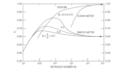
The dimensionless discharge coefficient is the ratio of actual and theoretical flow through the meter (Cd = actual/ theoretical). It's caused by friction and also by the fluid stream contracting past the restriction. Therefore, the vena contracta area is less than the opening area of the restriction (orifice), and Cd rises as the convergence angle is reduced. Typical values are: orifice = 0.61, flow nozzle = 0.90, venturi = 0.986. For orifice plates, Cd tends to be fairly constant at 0.6, as long as the Re is greater than 10,000. It increases a little faster as the beta ratio (Β = orifice diameter divided by/pipe diameter) (Figure 1).
As Re drops, measurement error rises. For this reason, when I size an orifice plate, I always calculate Re at both the maximum and minimum flows expected. And if the minimum Re is below 20,000, I use another type of flow sensor. At Re = 20,000, the Re error is about 0.5% of actual flow, meaning that the Cd is 0.5% higher than maximum.
Naturally, flow velocity changes aren't the only error sources in orifice-type measurements, since pipe configuration, pressure tap types and internal roughness of the pipe also affect the Re (see Moody diagrams). Here, I will not cover the complicated topic of friction factor calculation, but a lot of experimental data exist on this subject. The friction factor comes into play when the pipe wall is not smooth and the fluid closer to the walls is held back due to this additional shear. This, in turn, causes the velocity profile to become flatter and blunter as increasing roughness increases flow velocity.
You can see that the relationship between flow profile and measurement error is a complex one. So, when I have a critical application, I require calibration of the assembled complete system, including upstream and downstream piping and straightening vanes, if any. In addition to the sensor, the total error will include contributions of other loop components. As far as the transmitters are concerned, both their accuracy and rangeability have much improved during the last decades, but these don't reduce total error, they just add less error to it.
Béla Lipták
[email protected]
A2: You'll find information related to this question at the links below:
- fluidcomponents.com/assets/media/Technical-Articles/Transitional-Flow-Effects.pdf
- mccrometer.com/technical-articles/challenge-of-flow-disturbances-meter-accuracy
- mccrometer.com/technical-articles/how-to-get-accurate-flow-measurements-despite-flow-disturbers
- piprocessinstrumentation.com/instrumentation/flow-measurement/article/15564010/5-factors-that-impact-thermal-mass-flowmeter-accuracy-flow-profile-and-conditioning
Alejandro (Alex) Varga Meder
Senior Project Manager
[email protected]/[email protected]
Q: Dear sir, Venturi tubes are designed for volumetric flow rate measurement. If we want to measure mass flow rate, we generally have to multiply the reading by density. But for gas service, density varies with pressure and therefore differential pressure across the Venturi tube also varies.
What options do we have to derive an accurate gas mass-flow measurement when the molecular weight of gas also varies and we need to make a compressor surge calculation?
Kindly help me out. Thank you very much in advance
Abhishek sharma
Process Engineer
HMEL India
A1: For cases where density is varying, we have the following options:
- Implement a compensated flow gas measurement with a gas density instrument, where you should make a math calculation of flow in the DCS.
- Evaluate the possibility of building a characteristic curve of density vs. differential pressure (DP) in order to yield a flow value according the DP pressure. This can be implemented in the transmitter.
- Implement a flow mass measurement with a Coriolis flowmeter instead of a Venturi meter.
Kervin Peña
[email protected]
A2: I'd suggest that one reference is the AGA for flow calculations of natural gas via orifice plates (e.g., A.G.A. 3 “Orifice Metering of Natural Gas and Other Related Hydrocarbon Fluids”). With regards to the compressibility factor (Z), there are some calculators for this as well, so one can then calculate mass flow.
Simon Pate
[email protected]
Carrier Corp.,Detector Electronics
A3: Most compressors use Venturi meters on the discharge because they have a low sustained pressure loss and are accurate. Coriolis meters aren't used because, when a compressor approaches surge, the flow is “surging,” which makes Coriolis meters inaccurate; they read high when vibrations go up.
For many compressor applications, the gas purity or gas density is measured separately on the inlet, and this value is updated (after validation) to the anti-surge controls. The Venturi differential pressure, discharge pressure, discharge temperature and density inputs are brought into a PLC or fast controller to calculate the volumetric flow, polytropic head, surge line, and the output to an anti-surge valve.
If the gas composition is changing, there isn’t any easy way to get around the requirement for a gas-density or composition measurement.
Ralph J. McCloskey
Chief Engineer – Process Control Center of Excellence
Honeywell Process Solutions
[email protected]


