The secret to improving process performance is getting the right mass flows and component concentrations in process streams as seen in your process flow diagrams (PFD). Unfortunately, the most common flow measurements are volumetric. While pressure and temperature compensation can be used to compute a mass flow from volumetric flow, the compensation is based on the stream’s assumed composition and physical properties.
There are many installation effects that cause a poor signal-to-noise ratio, and losses in accuracy and rangeability. The most notable is the effect of piping and valves upstream and, to a lesser extent, downstream. Volumetric flow measurements by differential pressure (DP) and vortex flowmeters are also sensitive to velocity profile, viscosity, density, low Reynolds number, bubbles and solids. Also, accuracy is expressed in percentage of span. Because pressure drop is proportional to flow squared, it can make the DP flowmeter signal-to-noise ratio at low flows exceptionally poor. DP flow meters are also vulnerable to many problems with impulse lines.
Magnetic liquid flowmeter (magmeter) performance isn’t sensitive to application conditions that adversely affect other volumetric flowmeters. Magmeter accuracy is a percentage of reading with consequently less deterioration at low flows, and rangeability is five times better than what’s stated in publications for DP meters that don’t account for significant deterioration in performance due to installation and application conditions. Magmeter performance can be 10 or more times better than a DP meter.
A Coriolis meter is a true mass flowmeter with accuracy and rangeability five times better than a magmeter with an accuracy in percentage of reading that, like a magmeter, isn’t affected by installation and most application conditions. Problems with cross talk and pipeline support were solved in the 1990s. Coriolis meters can handle small amounts of bubbles and particles in liquid streams. No maintenance is generally required after initial calibration. Another incentive is extremely accurate density measurement that can be used as inferential measurements of component concentration, notably in raw material feeds, recycling and product streams.
A worthwhile investment
However, Coriolis meters’ upfront costs are greater than DP meters, especially for larger lines. Nonetheless, if you consider eliminating maintenance and their extreme accuracy in mass flow and composition control, investing in Coriolis is justified by their reduced lifecycle costs, and improvements in process capacity and efficiency. The fact that Coriolis flowmeters are limited to 14-inch or less line sizes can be addressed by having multiple Coriolis meters in parallel lines.
Process pressure higher than specified for a flowmeter can result in a span error due to increased in flow-tube stiffness. A process temperature different than what was used in the factor calibration of the meter can cause a random error in the zero value.
Well-defined online pressure and temperature compensation is possible in these situations.
Coriolis flowmeters are available in high-pressure and high-temperature models with a variety of wetted materials. If a Coriolis meter tube suffers from corrosion and/or erosion, diagnostics have been developed to detect the onset and extent of the problem. Plugging one tube in a dual bent-tube meter reduces accuracy but doesn’t disable the meter. The use of a straight-tube instead of a dual bent-tube meter reduces the adverse effects of erosion and plugging. However, straight-tube meters aren’t as accurate as dual bent-tube meters.
Pros and cons and considerations
For more on how Coriolis meters can deal with challenging installation and process conditions, see the Control Talk column, “Knowing the best is the best” and my ISA-published book, Essentials of Modern Measurements and Final Elements in the Process Industry.
The following excerpts from my McGraw-Hill-published book, Process/Industrial Instruments and Controls Handbook sixth edition, provides additional guidance often not detailed in other articles and books.
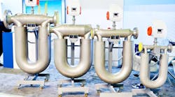
Dual bent-tube sensor benefits include:
- Excellent accuracy, repeatability and measurement range for flow and density;
- Excellent mechanical system balance and strong signal-to-noise ratio;
- Excellent immunity to field effects, such as plant and pipe vibration; and
- Minimal (or no) thermal stresses or mounting effects.
For these reasons, this style is often preferred for custody transfer, gas flow and variable flow regimes, including two-phase flow such as entrained gas in liquid or entrained liquid in gas (mist).
Dual bent-tube sensor disadvantages include:
- The flow splitting manifold and long tube length contributes to additional pressure losses;
- If one tube becomes plugged, it’s difficult to clear or mitigate blockages without mechanical intervention; and
- The deeper flag length requires more clearance around the pipeline.
Single straight-tube design: Straight-tube sensors are often constructed from premium materials (such as titanium), which provide low thermal expansion in a constrained space and flexibility to maximize resolution from limited tube movement. Straight-tube sensors constructed of other materials, such as stainless steel, are more susceptible to thermal stresses, which can affect flow and density accuracy at process conditions that differ from calibration process conditions.
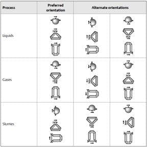
Orientation
Additional installation considerations:
- Coriolis sensors are considered bidirectional.
- For liquids and slurries, flowing upward is recommended.
- For gases, tubes up or flow downward is recommended.
- Control valves should be placed downstream of the meter, and as close as possible to the meter to avoid unnecessary holdup volumes.
- Don’t use the meter to align pipework, and minimal torsional stress should be applied.
- No external supports are needed for the sensor body. The flanges will support the sensor in any orientation. Some small sensors are available with mounting brackets to simplify installations using flexible tubing or wall-mounting.
Flow conditioning
No upstream/downstream flow conditioning is required. However, if two-phase flow exists occasionally, best performance will be achieved by ensuring that the fluid is homogenously mixed and divided equally into both sensor tubes. In this case, it’s recommended that a blind T or static mixer be placed upstream of the meter.
Calibration and maintenance
Coriolis meters are extremely linear compared to most other flow technologies. Each Coriolis meter has one unique set of calibration constants that apply equally across the entire measuring range of the meter, including a mass flow calibration factor (FCF), density calibration factors and temperature and pressure constants. It’s generally not necessary to specify that custom flow rates or custom fluids be used during calibration or to linearize the calibration.
In general, anything that causes a change in stiffness of the sensor tubes will affect the vibration qualities of the sensor. Erosion and corrosion can be mitigated by sizing the sensor properly and by selecting compatible materials, but process temperature and pressure also affect tube stiffness. Most Coriolis manufacturers include a resistive thermal device (RTD) inside the sensor to measure the temperature of the tubes, and apply a temperature compensation factor to correct for the change in tube movement due to temperature. Expect to find unique thermal expansion coefficients for flow (FT) and/or density (DT) published by the manufacturer. Also, expect to find unique pressure effect coefficients published by the manufacturer to account for expected offsets in the measured flow and density values at high pressures.This is primarily a concern for larger sensor sizes with larger internal surface areas to contain fluid pressure.
Coriolis sensors typically don’t include any user-serviceable parts, other than electronics. For critical applications, maintain a complete spare flowmeter in the event of a suspected component failure or perceived measurement offset. To discriminate between perceived issues and true equipment failures, Coriolis manufacturers offer in-situ diagnostic capabilities to help verify meter functionality in the field.
Drive gain is a useful diagnostic variable. It indicates the amount of electrical current the drive coil is using to maintain the sensor vibration at its harmonic frequency. Typical drive gain values for clean fluids are typically low (<10%), but any value under 100% means the sensor has achieved the desired vibration profile using available energy. However, if the drive gain reaches 100%, this indicates the sensor is out of balance, and the drive coil is unable to control the sensor’s vibration using even the maximum available current. A 100% indication is typical when corrosion, erosion or coating has developed, when one of the tubes is plugged, or when large changes occur in the process. These changes include valves opening or closing swiftly (brief spikes) or tubes that aren’t full (i.e. slugs or gas bubbles). They also include rapid changes in the fluid’s properties, such as interface between two fluids of differing densities.
Known density
This is a technique that can be used in the field to verify density performance and structural integrity of Coriolis sensors within a reasonable expectation of error. The theory holds that, if you fill a sensor with a known density fluid under controlled conditions and the sensor accurately measures the fluid density and the sensor is in otherwise good condition (i.e. no physical changes or damage has occurred), then the sensor is likely capable of making good flow and density measurements. Any change to the sensor’s vibration qualities is indicated in the measured density, which is more sensitive to errors from structural changes than flow.
Sensor tube integrity is a newer Coriolis diagnostic technique (often called meter verification) that drives the sensor tubes at a series of test frequencies, and compares the response to a set of reference values determined when the sensor was in a known and good condition. Because the meter’s electronics are required to drive the test tones and interpret the sensor response, this also verifies that the electronics are working properly.
Latest from Flow
Latest from Flow


