Q: A fuel gas package (FG1) was going to supply four turbines through an orifice flow transmitter (FT100). Another fuel gas package (FG2) supplied two turbines across a vortex flow transmitter (FT200). Total fuel gas consumed is the addition of individual fuel package (FG1 and FG2) consumption. Then, if all flow is across (FG2), I have less total fuel gas consumption. Why is flow through only FG2 not the same as the total fuel gas consumption compared with FG1?
- FG1 orifice flowmeter: 0-150 ksm3/d
- Pressure upstream: 29.5 bar
- Pressure downstream: 20 bar
- FG2 vortex flow transmitter: 0-9,000 kg/hr
- Pressure upstream: 29.5 bar
- Pressure downstream: 21 bar
Get your subscription to Control's tri-weekly newsletter.
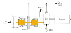
A1: In my handbook, when you look at a chapter dealing with a unit operation (reactors, distillation, boilers, etc), it always starts with a detailed description of that system. In this question, one can’t be sure of the piping/valving configuration of the discussed system, so we must make assumptions. I assume your installation involves measuring fuel gas flow to four turbines, and Figures 1 and 2 describe their configuration and control.
I assume the load on each of the four turbines is determined by the gearbox speed controller, which positions the throttle valve in the fuel gas supply lines of each of the four turbines (Figure 1).
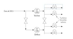
Figure 2 shows the assumed piping/valving configuration of the two gas flowmeters, which measure total gas flows to the four turbines in one of two ways. I say assumed because the wording of the question doesn’t describe it.
The assumed Configuration 1 (C1) is obtained, when the total gas flow to the four turbine throttle valves is measured by the vortex flowmeter (FT-200) in Figure 2. This configuration is obtained when valve (V1) is closed and valve (V2) is open. Configuration 2 (C2) is obtained when V1 is open and V2 is closed.
First, I’ll discuss how this strange piping/valving configuration could have evolved. It’s possible the initial installation included no vortex flowmeter (FT200), no valves (V1 and V2), and the orifice meter measured the total flow to all turbines. Next, as is often the case, the demand for total flow increased, and the 3:1 rangeability of the conventional orifice type measurement became insufficient. At that point, instead of replacing the orifice with a larger one or replacing the conventional DP cell with a higher rangeability smart transmitter, the users kept using the existing orifice, and added this strange bypass shown in Figure 2, consisting of a vortex meter and valves V1 and V2.
Both the orifice and vortex flowmeters detect volumetric flow, while the flow of interest to the turbines is mass flow;
The readout range of the two flowmeters isn’t the same because the vortex is in kg/hr and the orifice is in m3/day; and
The flow measured by the vortex meter is about half as much when the system is in C2 than in C1, so it’s possible that in C2, the Reynolds number drops below the required 30,000 limit, increasing the measurement error.
The bottom line is: what you have is no good, and should be replaced with a single, high-rangeability, mass flowmeter, such as a Coriolis meter.
A2: In general, I expect the orifice flow measurement to have a greater chance of error than the vortex flow measurement. This is more likely with older flowmeter installations due to errors accruing from wear of the orifice (loss of the sharp edge in the orifice), the error resulting from the sensing of downstream pressure not being at the vena contracta, or the location downstream of the orifice, which is the lowest pressure. The location of the vena contracta varies with flow rate. Orifice taps are most likely to have the most vena contracta error.
In my process control classes, I tell my students that using orifice meters for flow control is the most economical measurement technology because, for control purposes, vena contracta error makes no difference. However, don’t use these measurements for material or energy balances because they can be in error by as much as 4%.
Vortex-shedding flowmeters are, in general, more accurate since they have no elements that wear with flow. However, even vortex meters shouldn’t be used for material and energy balances because they’re only 1-2% accurate. Only Coriolis, turbine or positive displacement flowmeters are accurate enough for material and energy-balance purposes.
This application seems to be related to accuracy of measurement. In that case, none of the flowmeters you’re using can provide accurate data.
This column is moderated by Béla Lipták, who also edits the Instrument and Automation Engineers’ Handbook, 5th edition, and authored the recently published textbook, Controlling the Future, which focuses on controlling of AI and climate processes. If you have a question about measurement, control, optimization or automation, please send it to [email protected]. When you send a question, please include your full name, job title and company or organization affiliation.
About the Author
Béla Lipták
Columnist and Control Consultant
Béla Lipták is an automation and safety consultant and editor of the Instrument and Automation Engineers’ Handbook (IAEH).


