Q: I’m participating in an industrial research project in southern Spain, which uses parabolic trough collection of solar energy. Thermal oil runs through the collection lines, which are solar heated, and the hot oil generates steam for turbo-generated electricity production. The oil is circulated by a centrifugal pump using a variable-frequency speed controller. At noon, a higher oil-circulation rate is needed. During lower-irradiance mornings and afternoons, slower pump speed is required.
The oil circulation rate has a 2:1 ratio, but since the required fluid power is proportional to the cube of the flow rate, the pumping power has an 8:1 ratio. The pump is a power “parasite.” Given fluid duty, its efficiency peaks at one speed, and then falls in a parabolic-like manner for higher or lower speeds. Our simulations indicate, rather than one large, centrifugal pump, if there were several smaller pumps in parallel, they could all run during high-circulation periods. We could turn off some during lower-circulation periods to provide fluid power, which would permit those operating pumps to run at speeds closer to their efficiency peaks, reducing the parasitic power demand.
Get your subscription to Control's tri-weekly newsletter.
Have others implemented such a scheme? Is there a best number of smaller pumps? Are there mechanical or control issues with switching pumps on and off? Does this scheme provide an energy savings that justifies the overhead and initial capital cost? Because this scheme lessens operating time on pumps, does this have a measurable economic impact on pump life and maintenance costs?
R. Russell Rhinehart, emeritus professor, Oklahoma State University / russ@r3eda.com
A: Before answering the specific question, I’ll discuss pumping station controls and their selection in general.
System curves
A pump is a liquid transportation device, which must develop enough pressure to overcome the hydrostatic and frictional resistance of the process into which it delivers the required fluid.
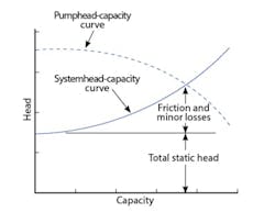
The head requirement at a certain flow is the sum of the static and the friction heads that the pump must overcome. Pumping systems are categorized according to the location of their operating point on a head-to-flow plot (Figure 1). The static head portion (Hs) of the total head (Ht) doesn’t vary with flow rate because it’s only a function of the elevation or back pressure the pump is operating against. On the other hand, friction losses increase with the square of flow, and tend to be steeper if the piping is undersized or dirty.
I assume Dr. Rhinehart's application falls into Zone 4 in Figure 1 because the oil is circulated in a horizontal plane, where there’s practically no Hs and the system curve parabola at zero flow is zero. As the zone numbers drop, the friction component of the total head also drops.
When the system curve is flat (Zone 1), there’s little advantage to using variable-speed pumping. On the other hand, in processes where the system curve is steep (Zone 4), substantial energy savings can be obtained by using multiple, variable-speed pumps, which start and stop as a function of required flow.
Centrifugal pumps
Centrifugal pumps use centrifugal force to throw liquid radially outward. They have high efficiency of up to 90% in case of some large pumps, but generally between 60% and 85% as a function of pump design and size. They have only one moving part (the impeller with bearings), deliver steady flow, have a rangeability of 4:1, and are relatively insensitive to air-locking. However, they are susceptible to cavitation.
The shape of the head-capacity curve can droop, be flat, or be normal. For this discussion, I assume the pump curves are normal, stable at all flows, and suited for throttling services. Figure 2 shows the head-capacity curve of a constant-speed, centrifugal pump (dotted line) and a system head-capacity curve of an assumed process (solid line). In case of constant speed pumps, the dotted pump curve is fixed, and the operating point is where the pump and system curve lines cross. A fixed pump curve is the only way to change the flow (Q). In the case of constant-speed pumps, this can only be done by placing a throttling control valve on the pump discharge, and artificially increasing or decreasing the total friction loss of the of the system (Figure 2). In this configuration, the pumping energy required to overcome the pressure drop through the control valve is wasted energy, which can be eliminated by using variable-speed pumps.
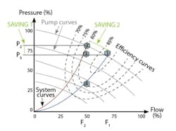
Switching from constant to variable-speed pumping can save in two ways. Figure 3 shows both, as well as the system curves for constant (red) and variable-speed (blue) pumping.
In the case of the red system curve (constant speed), when the flow must be reduced from F1 to F2, the pump discharge pressure has to rise from P3 to P2. The increase is introduced by further closing the control valve on the pump discharge. Overcoming this increased pressure drop wastes energy, which can be eliminated by using variable-speed pumps (Saving 1 in Figure 3).
In the case of using variable-speed pumps (blue system curve in Figure 3), reducing the flow from F1 to F2 is achieved by reducing the pump speed to Point 4. This eliminates the need for throttling or even having a discharge valve (Saving 1). However, it also produces Saving 2 because the red system curve operates on a less efficient point on the pump curve (80% efficiency at Point 2) than the blue system curve (85% efficiency at Point 1).
Users must consider the overall system efficiency index (SEI) of the installation, which is the product of the efficiencies of the pump, motor, variable-speed drive and utilization efficiencies
They must also consider if the 4:1 rangeability of a single variable speed pump is insufficient, and whether to use multiple smaller pumps that are less efficient.
Béla Lipták / liptakbela@aol.com


