Q: I want to know more about differential pressure (DP)-type level transmitter calculations and calibrations, so I can better understand how to correctly make low-range value (LRV), upper-range value (URV) and zero-shift settings.
J. Aashok, instrumentation engineer / [email protected]
Get your subscription to Control's tri-weekly newsletter.
A1: The nuclear accident at Fukushima Daiichi is a good example of such an event, but before describing it, I’ll make some general points about level transmitters (LT) and the terminology used when providing the process data describing the liquids they measure and their installation.
For dry-leg applications, you should provide the specific gravity (SG1) and expected pressure/temperature ranges of the process fluid. For wet-leg applications, you should provide the specific gravitie of the process fluid (SG1) and of the wet-leg fluid (SG2). Then, you must select an LT that has a range larger than the span required for the application. The span is defined as the difference between the pressures the LT detects on its high- and low-pressure sides. The output signal from the LT corresponds to the difference between the upper- and lower-range values (S = URV - LRV). LT accuracy is a percentage of its range, which should n’t be much larger than the application’s required span.
Regarding the process fluid, you should provide safety, toxicity and plugging data, and report if bubbler components, chemical seals, pressure repeaters, or regular or extended diaphragm seals are required. You should also specify the elevations of the lower- and the upper-pressure taps, and the height of the wet leg, if any.
Below are some considerations you should remember:
-
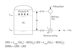
It must be understood that all LT installations have two setpoints and two zeros. One zero is the level in the tank (Lmin) and the other is the pressure difference detected by the LT. If the elevation of the LT and that of the bottom pressure tap on the tank are the same, the two zeros will be the same (Figure 1).
-
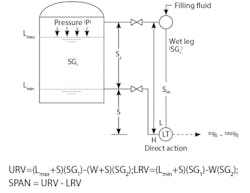
If the elevation of the transmitter is above or below the pressure tap on the tank, or if the specific gravity of the process fluid (SG1) differs from that of the wet-leg (SG2) suppression, the elevation the LT span is required. As shown in Figure 2, suppression (S) is needed if the LT elevation is below the lower pressure tap on the tank. In that case, the zero of the LT must be suppressed by the difference between the maximum span (Sm) and the calibrated calibrated span (Sc), which is the distance S shown in Figure 2.
- The LT action must also match the application. It’s usually direct, if dry-leg installation is used, and reversed for wet-leg installation. If the LT elevation is below the lower pressure tap, the zero of the LT is suppressed. The amount of the suppression equals maximum span minus calibrated span (Sm - Sc).
- For the dry-leg applications, make sure the proccess vapors don’t condense. One method is to use pressure repeaters to isolate the vapor space in the tank and the vapor above the wet leg. Also, for wet-leg applications, make sure the leg is always full because the fluid in it is heavier than the process fluid and doesn’t evaporate or boil due to solar exposion or for other reasons.
- In case of an unusual wet-leg installation, where the LT is installed above the process tank, the LT action is a function of the net combined effect of the elevations of the transmitter and the lower pressure tap.
- Make sure the supplier correctly calibrates the transmitter, so the transmitter's span suppression corresponds to the difference between the upper- and lower-range values (LRV - URV).
- To protect against corrosion, toxicity or plugging, consider pressure repeaters or chemical seals.
- The zero, span, elevation or depression can be adjusted on mechanical or electronic LTs (Table 1).
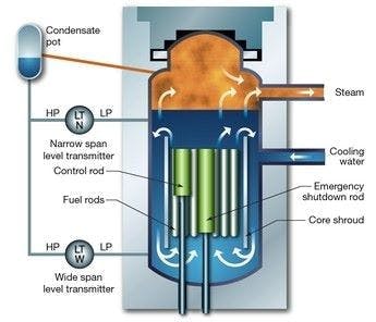
Accidents are often casused by errors in LT measurements, and some of the worst consequences can be losing process cooling. This occurred at Fukushima, where reactor overheating caused boiling in the wet leg. The resulting water loss in the wet leg caused the LT to report a rise in the cooling water level in the reactor, when in fact it was dropping (Figure 3).
Béla Lipták / [email protected]
A2: It would be very difficult to keep the high-pressure sensing line filled only with gas. I prefer to use remote chemical seals in this service.
Cullen Langford, control specialist / [email protected]
A3: If your high-pressure leg is diaphragm-sealed and filled with an inert transfer fluid, the pressure on the high-pressure side of the LT will be the head (pressure) of the transfer fluid plus the head of the liquid in the tank plus the vapor space pressure. The LP side will see only the pressure of the vapor space. Since the head pressure in the HP leg is constant, it can be removed by setting the zero point of the LT.
Richard H. Caro, ISA life fellow / [email protected]


