This column is moderated by Béla Lipták, automation and safety consultant, who is also the editor of the Instrument and Automation Engineers’ Handbook (IAEH). If you would like to become a contributing author of the 5th edition or if you have an automation related question for this column, write to: [email protected]
Glai Mendoza
[email protected]
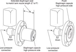
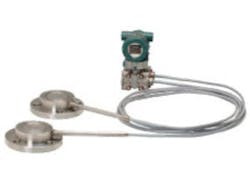
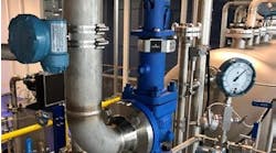
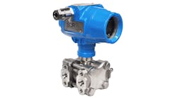
A: I had no leakage problems with the many flat or extended diaphragm d/p transmitters, which I have used on viscous, sludge, slurry or other plugging services (Figure 1). If the low-pressure side of the d/p cell also required protection from plugging I also often used dual chemical seals (Figure 2), which are convenient if one wants to locate the transmitter above or away from the tank.
Also Read: Guided Wave Radar vs. Differential Pressure Transmitters for Liquid Level
Béla Lipták
A: I see two questions. The first is the structural one. Designed and fabricated per the codes and standards, pads have been used for a long time and are considered reliable and safe. The only disadvantage I see is that the threaded holes for the studs could be damaged and are difficult to repair.
The instrument issue is that without a nozzle to accumulate "stuff" the measurement might be somewhat more reliable, especially if the pressure connection is a remote diaphragm.
Beyond that, I see no problems unless there are other significant aspects not mentioned in the question.
Cullen Langford
[email protected]
A: By your mail, I understand that you have a chemical seal capsule and capillary connected transmitters. If so, we have used these without any problem of leakages or extra maintenance issues. However you may need a block-and-bleed manifold to release the pressure before you open the flange, for sake of safety.
H S Gambhir
[email protected]
Q: Straight pipe run for conditioning orifices
I am supposed to install an orifice plate to measure the water flow in a pipe, which is 0.3 m above ground. Therefore we do not have room to install the d/p transmitter below the pipe. Is there any way to locate a d/p transmitter above the pipe tapping point?
As per ISO 5167 we should provide straight up and downstream pipe run, but we don’t have enough space for this either. What should we do? Rosemount has a new model orifice plate that needs only 4 pipe diameters total upstream and downstream, but I can’t find anything about its pressure drop. Is there a way I calculate its pressure drop?
Also Read: Sealing an Oil Well; Orifice Sizing--OSO versus AGA
Hassan Mommadzadeh
[email protected]
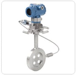
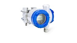
A: The Rosemount compact orifice meter design (Figure 3) allows one to locate the d/p cell above the pipe. The manufacturer claims that the inaccuracy of this flowmeter is under 1% of actual flow over a flow range of 8:1 and that it requires only two straight pipe diameters up and downstream when installed. I emphasize that these capabilities are only claimed by the supplier, and I have not seen any reports from any independent testing laboratories that supported these claims. Similarly, the claim that two pipe diameters of straight pipe are sufficient both up and downstream is hard to believe, and I would like to see that substantiated by independent testing when 90º elbows are up and downstream.
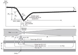
My understanding is that the up- and downstream pressures are measured by corner taps right on the two sides of the orifice plate, and therefore, the performance is likely to be similar to corner tap installations (Figure 4).
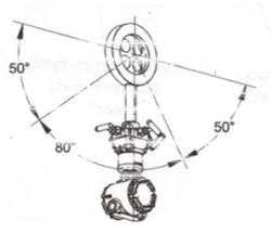
As shown in Figure 5, the transmitter has to be installed 50° below the horizontal (to protect against gas accumulation). You probably have enough room to do that, but if your water is not clean, I would not use this flowmeter design, because of the plugging of the pressure taps.
As to pressure drop, it is similar to that of the traditional orifice at the same beta ratios.
Béla Lipták
A: A horizontal take off from one side will work adequately. A slight slope (1:10) up to the tapping points will ensure any air bubbles can be displaced.
The Rosemount conditioning plates DO work, and I have had several installations immediately downstream from pump/check valve assemblies (6 D, 2D) which checked well against a turbine meter - minimum-flow installation within a piping layout that forgot the meter runs!
Permanent loss is close to that of a single orifice with the same nominal beta and dp. The sizing equation gives this.
Ian H. Gibson
[email protected]
A: Use the Darcy Equation (an approximation only, because velocity immediately at the outlet of the orifice is unknown. Normal calculation of outlet velocity is based on mature velocity profile, such as at 10D downstream of orifice):
[(2.gc.144.ΔP) / ρ] = 1.5 v2
where v is the inlet velocity in feet/second
P is pressure in psi
ΔP is pressure drop in psi
p is density in lbm/ft3
gc is universal gravitational constant, 32.2 (lbm ft)/(lbf.s2)
1.5 is the loss coefficient of the orifice plate with 4 holes. (Reference to Crane Technical Publication 410, inlet loss coefficient of sudden contraction is 0.5; outlet loss coefficient of sudden expansion is 1).
These four holes are in parallel. Therefore, their effective loss coefficient equals to that of one orifice (of equivalent hydraulic radius due to the four holes).
The loss coefficient due to line loss is usually negligible compared to the loss coefficient of the orifice.
Additionally, note that the orifice plate with four holes was not in any approved standard.
I hope to see experiments showing 4D is all that is required for establishing mature velocity profile for the orifice plate with 4 holes.
Gerald Liu, P. Eng.
[email protected]
A: To connect the DP transmitter to the orifice plate for all liquids, the connection must be under the midpoint of the pipe to avoid air/gas entrapment in the sensing line.
All meters will require some upstream and downstream pipe sizing. With flow conditioners, you can reduce the upstream/downstream lengths to minimal lengths, but still some.
The orifice arrangement by Emerson/Rosemount has a flow conditioner in the orifice plate holder arrangement. The accuracy in such a flow transmitter will be dependent on the stability of the flow as well as having as little variation as possible of the process variables. The conditioner compensates for upstream and downstream lengths in the conditioning section, which is generally much less than the standard upstream and downstream pipe lengths.
One thing to take into consideration is that such a conditioning element, be it a flow conditioner, flow vanes, etc., will make the transmitter/orifice plate arrangement more expensive, but with your constraints of dimensions it might be worth it.
Alejandro Varga
[email protected]
A: If you use a DP with remote diaphragm seals/capillaries and flanged tappings on the orifice flanges, you can mount above the orifice. You would have the tappings coming off the sides.
Discuss with the vendor, who would have the sizing program. This would be a specialist sizing program developed by the vendor and is not covered by industry standards or a generalized sizing program.
Simon Lucchini
[email protected]
A: I have not personally had an issue with not having the pipe tap below the pipe, but we once had a major issue with the lack of free pipe downstream. We had 4-5 D straight pipe downstream and then a 90° bend. The D/P cell told us we had reverse flow of water, which could not happen in a 500-PSI pressurized system. The eddy currents at the elbow really messed up the flow measurements.
Bruce Land
[email protected]

