What's wrong with my thermocouple? How do I know my RTD measurement is accurate?
Q: Thermocouple Diagnosis
Our Type K thermocouple at 25 ºC generates 1.0 mV. It has a long TC cable which does not show continuity, but 130 ohms resistance. Can you explain why this is occurring and how it can be fixed?
Ashish Garg
[email protected]
A: One of the problems associated with long extension wires is noise interference. The best alternative is not to send low-level TC signals over long distances, but to place the transmitter electronics directly on top of the thermowell. Today the use of integral transmitters in most industrial applications is competitive in cost and can actually cost less than running long thermocouple lead wires to the control room.
This column is moderated by Béla Lipták, automation and safety consultant, who is also the editor of the Instrument and Automation Engineers' Handbook (IAEH). If you have automation related questions send them to: [email protected].
Read other Ask the Experts articles.
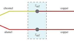
Figure 1: K-type thermocouple (chromel–alumel) in a configuration where the measured voltage V is used to calculate temperature (Tsense), using the known reference temperature (Tref).
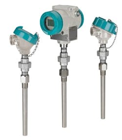
Today, wireless intelligent transmitters are also available in wireless designs (Figure 2). I would consider these for your application if the transmission distance is long.
Béla Lipták
[email protected]
A: The thermocouple is a dc voltage source with the voltage determined by the temperature difference between the hot junction in the measuring head and the cold junction created by applying the measuring instrument leads. The net potential at the measuring terminals and/or the total resistance of the circuit may interfere with the proper operation of the continuity tester and yield ambiguous or no results for you.
Figure 2: Wireless and intelligent temperature transmitter.
Courtesy of Siemens
An ohmmeter consists of a current source, often a fixed voltage, and a series-connected, current-limiting range resistor and a voltmeter connected across its terminals. Connecting the terminals to an unknown resistance causes a proportional voltage across the terminals to the unknown resistance (R? = E(measured)/I(known)). In case of a thermocouple (TC) installation, the unknown TC circuit resistance is masked by its series-connected, temperature-difference-dependent, hot junction minus cold, half-junction voltages. The voltage measured by the ohmmeter and therefore the indicated resistance will be affected.. Make one measurement using the positive ohmmeter terminal connected to the positive thermocouple, noting the reading. Then repeat the test connecting plus to minus and note the second reading. Add the two readings together and divide the sum by two. The result will be the circuit resistance.
Otto Muller-Girard, PE
[email protected]
A: Please confirm what the length of the T/C from the junction to wherever it is connected to is. I assume that the T/C sensor is connected to a 3-wire cable with only two wires connected at the sensor. I also assume that all three wires are connected to the terminals of a junction box, and the three wires at the terminals are connected to the final instrument.
The overall resistance of the T/C depends on the size of the internal wire, which is generally between 20# AWG to up to 30# AWG, and on its overall length. As an example, the overall resistance of a 300-mm long, 22# AWG TC wire has an overall resistance of 0.9238 x 300 = 0.922047244 ohms. The resistance for the T/C cable will be the overall length of cable in meters multiplied by the resistance of the selected extension cable size.
As to continuity:
- Check the continuity of the cable between the sensor head and the instrument receiving the signal. Remember to disconnect the sensor and receiving instrument. Just measure the cable continuity.
- Verify the T/C sensor continuity across the terminals of wires with the extension cables disconnected.
If for Item 1, there is no continuity but there is resistance, then you have a fault in the cable, since the resistance may mean that there is a ground in the cable somewhere along the route, and that the overall resistance you are trying to measure is so great compared to what you need that it means nothing. If for Item 2 there is no continuity, then the T/C is shorted.
Alejandro Varga
[email protected]
A: One must know the length of the thermocouple wire to determine the expected resistance, which is considerably higher than that of copper. However, this typically does not affect the accuracy of the reading. The word continuity does not mean zero ohms; it can mean any resistance value.
The thermocouple will not give a proper reading unless it is connected to a cold junction. Often people hook a thermocouple up to a millivolt meter directly, expecting it to read the correct millivolts. Since 25 Celsius is very close to ambient, the reading without a cold junction will be zero millivolts.
Bruce Land
[email protected]
A: Another option may be fiberoptic temperature sensors. They are not affected by distance.
Dennis Horwitz
[email protected]
Q: Surface-Mounted RTD Accuracy
A colleague of mine who owns a very accurate temperature measurement company asked if there is a method to calculate or quantify the total possible systematic/bias errors (differences in the accuracy) between an RTD mounted on a pipe surface vs. the accuracy of a wetted RTD that is inserted through the pipe wall into the process fluid.
Peter Baker
[email protected]
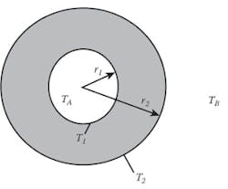
A: Heat flows in the direction of decreasing temperatures. All RTDs measure only their own temperatures. If the RTD is immersed into the process fluid, its temperature depends on the heat conduction to it from the process fluid and from it to the ambient outside. If the temperature of the process fluid in the pipe is higher than that of the outside air (TA > TB), the surface temperature in Figure 3 (T2) will be lower than the process temperature (TA). I am not aware of a specific equation or model for determining the differences in error or bias between immersion and surface sensing RTDs. The relationship between TA and T2 is a function of the following in constants and variables:
Figure 3: If the process fluid is warmer than the outside environment (TA > TB), the measurement of the surface temperature (T2) will read low and will underrepresent TA.
If there is no material buildup on the inside surface of the pipe, and there is no insulation on the outside surface of the pipe, the constants include the pipe radiuses (r1 and r2), the conductivities of materials A and B, while the variables include the changes in properties and velocities of materials A and B, their Reynolds, Prandtl and Nusselt numbers (which vary with the fluid properties). If all are known, difference (TA - T2), which is the error, can be calculated. Such calculations are complicated (See "Differences between measured pipe wall surface temperatures and internal fluid temperatures" and "18.5 Heat Exchangers"), but do exist and have been used in connection with heat exchanger designs. I know of no surface temperature detector supplier who provides such a model. What I have seen was users making spot checks and based on the measured ΔT, biasing their surface temperature measurements.Béla Lipták
[email protected]
A: In the surface-mount case, the calculation runs a heat balance from the loss of heat to the ambient air, to the influx of heat to the internal surface of the pipe through the external film coefficient (insulation sheath to air), thermal insulation over the sensor, heat transfer resistance of the metal, and the internal film coefficient. At each interface, the calculation will give a temperature. The difference between the outside of the pipe and the bulk fluid temperature is the error. The calculation is iterative, but rapid. In the range of 50-mm to 200-mm insulation around the sensor, the error is minor.
The thermowell error can be calculated similarly. One divides the length of the thermowell into (say) 10 annular sections. The heat balance on the well at each section comes from radial inflow from process fluid through a film coefficient plus axial inflow from the block below minus axial outflow to the block above. The atmospheric sink can be calculated by treating the flange as a fin surface (a horizontal flange gives only half the heat loss of a vertical fin surface). The model varies between the static fluid in the mounting nozzle and the active flow surface. This approach lends itself to calculating a step response for the well. The step response for the well plus element can be found with a minor extension of the model allowing for the heat transfer between well and element at each section. The old Kern heat transfer text has enough data to do the calculation.
These days, computer-based dynamic modeling tools are available.
Ian H. Gibson
[email protected]
A: In general, users avoid surface temperature except where there is no choice or where the surface temperature is the variable of interest, such as in the case of boiler tubes.
I would suggest that a thermowell (TW) in the fluid measures the temperature at and near the end of the TW. The purists will consider the effects of heat transferred to/from the TW from the outside. If the fluid is very turbulent, then the temperature across the flowing area will be close to constant, except near the wall, which is affected by the insulation and environment.. A measurement on the outside of the pipe will be affected strongly by all the details of the installation. Good insulation reduces the differences, which cannot be eliminated. The real issue is the uncertainty and the fact that insulation usually deteriorates over time. Like most things, the basic problem is that as the cost of a measurement drops, its uncertainty rises rapidly.
Cullen Langford, PE
[email protected]
A: Many papers have been written about heat transfer in heat exchangers, including the effects of various films forming on the wet wall. These papers apply to a surface-mounted sensor if there is heat flow through the pipe wall. But if conditions are static, and if the pipe and sensor are covered with adequate insulation, then there is no heat flow, and films (fouling) do nor matter. This is not likely to be the situation in industry, so you are left with the problem of the heat transfer coefficient of the fouling material. If the flow is slow or the pipe is very smooth, then laminar flow effects enter the equations, so surface-mounted sensors require near-ideal conditions to be able to calculate the errors. The problem becomes more difficult if the temperature is changing, because then the equations add the mass of the materials, and the sensor must be in intimate contact with the pipe, as a microprocessor is to its heat sink.
If the sensor is in the fluid, it usually is in a thermowell that allows the sensor to be changed without shutting off the flow and isolating the pipe. Thermowells have also been studied, but are subject to various unknowns that make accuracy impossible to calculate. If the sensor is directly wetted in some low flow of a benign material, it may be possible to eliminate most of the heat transfer problems. On the other hand, many people find the measurement in a thermowell to be accurate enough for practical purposes.
The distinction must be made between static and dynamic situations. Thermowells introduce their own delay into the control loop, affecting the optimum tuning. This also applies to the mass of the pipe wall, in the surface-mount case.
Bill Hawkins
[email protected]
A: I am not aware of a specific method or white paper that discusses the differences in error or bias between immersion and surface-sensing RTD sensors. The problem is that when you are looking at surface temperature measurement, there are a significant number of variables that come into play. When discussing the accuracy of RTDs, it is good to remember the old saying, "The only temperature an RTD measures is its own temperature (i.e., the RTD element).” The goal is to get the RTD element to the same temperature as whatever you are trying to measure. This applies equally to immersion sensors and surface sensors.
For the sake of clarity, let's assume that the process temperature is higher than the ambient temperature, and that the immersion sensor is a tubular probe with a metal sheath and a filler material packed around the RTD element and connecting wires. In the case of this immersion RTD, the RTD element gains heat from the process through the probe wall and the filler material. This heat gain will continue as long as there is a difference in temperature between the RTD element and the process. While this is occurring, the same thing is happening between the RTD element and the connecting wires. Coming from a lower ambient temperature, the wires will remove heat from the RTD element as long as the temperature of the wires is lower than that of the RTD element. So for immersion RTDs, there is a point at which the temperature around the RTD element is the same as the process temperature, and at this point there is no longer any heat transfer between the RTD element and the process or between the RTD element and the connecting wires. This condition is called thermal equilibrium, and the length of the sensor is referred to as the "minimum immersion length."
Surface sensors come in two basic styles: sensors with metal housings that clamp on to a surface and sensors with adhesive surfaces (let's assume a laminated construction) that stick onto a surface. The same conditions described above for the immersion sensor apply to these surface sensors. Heat is transferred from the surface to the sensing element either through the housing or through the laminated materials. Heat is lost from the element whenever the RTD element temperature is higher than the surrounding materials, and conversely, heat is gained by the RTD element when it is at a lower temperature than its surroundings. Unlike the immersion sensor, however, the heat flow from the surface (process) is limited to the area of contact, and the balance of the sensor is impacted by the ambient conditions. This creates the conditions where the sensor is far more exposed to a wide variety of thermal conditions and is why it is so difficult to provide a simple correlation between the two. Unlike the immersion sensor, which is generally only exposed to thermal conduction between the sensor and the process and ambient conditions, the surface sensor is much more likely to be affected by conduction, convection and radiational heating. Measures such as adding thermal insulation over the sensor to reduce ambient conditions can help, as well as placing the RTD element in as close as possible to the point of contact with the mounting surface.
This has been a very simplified explanation of what can be a very complex condition. At the end of the day, the best way to determine the accuracy of a surface measurement is to do a controlled experiment where the surface sensor's temperature can be compared to a known value.
Ron Desmarais
[email protected]
A: CFD (computerized flow dynamics) is a software program used to do the exact sort of analysis your friend is looking for. This subject was discussed most recently in an extended QA session on Automation.com about the effectiveness of surface measurement of temperature and what the user really desires. Is it the temperature of the skin or is it the temperatiure that relates to the thermal conditions of stuff under the skin that is of interest?
There are answers available to both questions. To see an example of CFD in action, go to Swifty Calc.
Any measure of temperature with any type of sensor is a surface measurement.
Frank L Johnson
[email protected]
