Regulating inlet fluid temperature
We want to input water into a collector in different temperatures, e.g., beginning from ambient temperature (20 °C), feeding the collector for, say, half an hour, then during a few minutes, change the temperature to 35 °C, keep it there for another 30 minutes, change it to 50 °C, etc.
We have a three-way valve with a regulator controlling the inlet temperature. One pipeline feeds it with cool water, and the other has an electric bypass heater. The heater cannot keep the water temperature fixed, but it fluctuates within a range of ±10 degrees.
I’ve planned to remove the heater and connect the other pipeline coming directly from the collector outlet. The other pipeline would still input cooled water. The whole system is closed, and includes a 200-liter tank with expansion unit.
The concern is that the outlet water temperature from the collector will not remain constant. This will set high demands for the valve and its controller to cope with the changing temperatures.
Does anyone know of any similar test facility? If so, does it work? Can you give me hints of another decent way to control the collector inlet temperature in a closed circuit?
Flow speed will remain constant during the test, although we want to test it with different flow rates. The minimum flow rate will be approximately 50 liters/hour and the maximum 600 liters/hour.
Petri Konttinen
ANSWER: The only chance of success is to use feed-forward control from temperature with feedback trim. If the three-way valve is perfect, i.e. the openings are perfectly linear with stem position and always add up to a constant Cv, the feed-forward model is simply
M = (Th – T)/(Th – Tc),
where M is valve position as a fraction of cold water to the total, Th and Tc are measured hot and cold water temperatures, respectively, and T is the set point of the blend. To add feedback, replace T in the equation with the output of the feedback temperature controller.
Any valve imperfection will lead to a feed-forward error and require action by the feedback controller. If the imperfection is systematic, the valve may be characterized to correct it. A digital positioner should be applied to the valve to eliminate dead band and other non-systematic errors. The dynamics of the feedback controller and any lead-lag feed-forward compensator may require scheduling as a function of total flow.
Greg Shinskey, Consultant
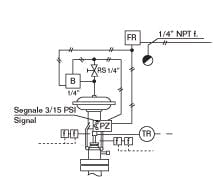
FIGURE 1: PNEUMATIC DIAGRAM OF A CONTROL VALVE
QUESTION: The figure to the right (Figure 1) is the pneumatic diagram of a control valve installation. Is a booster recommended for controlling the stroking time of the valve? My experience is that if the bypass valve (RS in Figure) isn’t in a good position, the booster can cause the valve to hunt continuously. Is it possible that after the initial adjustment of the control valve during startup, because with time the trim wears or process conditions change, the valve will start to hunt and require readjustment? The pneumatic positioner is a Fisher 3560 V/P. The booster is a FAIRCHILD Model 20512-DN1/4.
ANSWER:
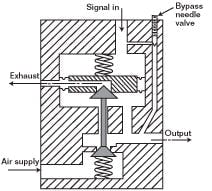
Large control valves and large actuators may require flow or pressure boosters installed between the positioner and the actuator to achieve the required speed of response without hunting. One special “dead-band booster” design is shown in Figure 2 below. It does not respond to an input signal change until an approximately 1 psi (6.9 kPa) difference is reached between input and output signals.
FIGURE 2: DEAD-BAND BOOSTER DESIGNIn this design, a built-in needle valve allows a limited airflow to bypass the booster gain portion of the relay and provides adjustable damping. In response to fast input signal changes, this booster provides large volume amplification, but it does not amplify a slow change.
One common application for this relay is in centrifugal compressor anti-surge controls, where the control valve must open very quickly (1 to 3 seconds), but after opening, it should throttle smoothly. The needle valve is adjusted when the complete control system has already been assembled and is in operation. Careful tuning is vital for proper operation. When the needle valve is fully closed and the loop is hunting, one should gradually open the valve until hunting stops.
Best operation occurs when the needle valve is open just enough to smoothly dampen the oscillations. If, in order to increase capacity, more than one of these relays is used in parallel, it is absolutely necessary to match the openings of the needle valves to avoid unstable interaction between the relays.
ANSWER:
I agree totally that the booster bypass valve (RS) has to be set properly, or the booster will create a valve stem cycle. I have seen some real problems there. We usually did not see the need for a volume booster until the valve was larger than maybe 8 inches or so, and the valve response had to be faster than standard.
I could not find that specific model number in the online Fairchild catalog to see the specifications. The sketch showed mostly ¼-in. tubing, and I have to ask if ¼-in. connections imply any possible real increase in air flow. In rare cases, we have installed larger connections on the valve actuator. The valve vendor might have an alternate actuator that might help.
Once in a while we discovered that the valve stem speed was being limited by the positioner supply air capacity. A plugged or undersized air filter can restrict response severely. We could make that judgment based on watching the three positioner gauges while the valve is being stroked. If a large change in signal pulls the air supply down very much, you have found the problem. If the positioner output pressure does not react quickly, take a close look at the positioner and find that problem. They can be maladjusted.
The valve stem cycle magnitude is a function of valve packing friction, and this can be reduced by changing to modern low-friction materials.
Cullen Langford, President, Cullen G. Langford Inc.
ANSWER: The combination of a booster in series with a positioner will result in limit cycle unless some of the input to the booster is bypassed around it. Some boosters have a built-in bypass adjustment. If not, one must be added (e.g. tubing and a needle valve). The bypass is opened until the limit cycle ceases now and in future operation.
The positioner output is normally looking into a relatively large actuator volume. When the positioner output goes into the small booster volume with its high inlet sensitivity, you end up with a limit cycle, unless you bypass enough of the flow around the booster so the positioner again effectively also sees some of the actuator volume. New digital positioners may be able to be tuned to help deal with this situation, so that not so much air needs to be bypassed. Bypassing air around the booster reduces its performance, so it is desirable to have it at the minimum needed to assure stability.
Greg McMillan, Principal Consultant, Emerson Process Management
| Ask the Experts |
|
Ask The Experts |
||
|
|
|


