Control of the solar-hydrogen plant
In this series of articles, I am describing the equipment and control requirements of the solar-hydrogen demonstration power plant. It would be time to build the world’s first solar-hydrogen demonstration plant, because it is time to stop the debate on the pages of newspapers and deal with factual data concerning the costs and efficiencies. Such a plant has not yet been built.
We are at a stage similar to the mid-20th century when John von Neumann developed the world’s first computer or when Leo Szilárd developed the world’s first self-sustained nuclear reactor. It took time for those discoveries to become understood, accepted and used. Similarly, it will take time for the clean and inexhaustible solar-hydrogen power plants to replace the fossil ones. It is up to all of us to speed the process because this time the stakes are even higher.
In this process, the optimized operation of each equipment block presents us with new process control challenges. For example, in order to obtain maximum energy recovery, the various solar collector all need to track the sun. The best control algorithm to use to position the individual collectors for optimized tracking is the envelope or herding algorithm, which I described in my January and November columns in 1998.
Thermal Solar Collector Designs
The thermal collectors on the roofs of private homes usually serve to provide the residence with heat and/or hot water. (A well-insulated house in the northeast U.S. uses about 1,000 gallons of oil (150 million BTUs = 44,000 kWh) a year for the purposed of heating and hot water.) The larger-sized thermal power plant designs on the market are either concentrating or flat. The concentrator designs—among many others—include parabolic troughs and dishes, central receivers and Fresnel lenses. This last design uses refraction instead of reflection. Their operation is either stationary or tracking, which increases the amount of energy collected by 30% to 40%, and their methods of conversion are either to convert the solar energy (photons) to thermal energy (heat) or directly to electricity (photons to electrons) by the photovoltaic process.
Here, the thermal designs will be described first. These designs are often referred to as solar-thermal-electric generating systems (SEGS).
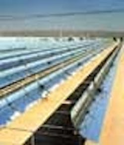
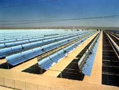
One of nine solar electric energy generating plants at Kramer Junction, Calif. The individual plant sizes run from 30 mW and up, with a total capacity of 354 mW. (Photo courtesy of Kramer Junction Operating Co.)
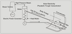
An example of that design is a 354-mW plant in operation at Kramer Junction and in Harper Valley in California since 1985 (See Figure 1). The main components and operation of the design is described in Figure 2 below (See Figure 2 below). In this design, parabolic mirror reflectors (troughs) are used to track the trajectory of the sun and to concentrate the sunlight onto absorber tubes that are located at the focal line of the parabolic mirrors. Inside the absorber tubes, heat resistant oil is circulated and serves to transport the collected heat into steam boilers, which provide the steam to drive the turbine generators.
In this particular installation, the hot oil circulates at 400 °C (752 °F), but there are higher temperature installations also. One advantage of the SEGS design is that the solar energy can be conveniently stored and used as needed to compensate for diurnal, seasonal and weather related changes in insolation. Several computerized control systems are in operation. These serve to optimize the positioning of thousands of mirrors to accurately track the trajectory of the sun and thereby maximize the collected energy. One such early installation was controlled by a Beckman MV-8000 DCS system (Beckman today is Emerson Process Management).
In some of the more recent SEGS designs, the circulating fluid temperature has been more than doubled, while in others direct steam generation (DSG) has been achieved, which increases the power production by some 15%.
FIGURE 2: TROUGH PARABOLIC CONCENTRATORPhotovoltaic (PV) Collectors
Sunlight is composed of photons containing various amounts of energy corresponding to the range of wavelengths within the solar spectrum. In the photovoltaic (PV) collectors, when photons strike the cell, they may be reflected, pass through, or be absorbed, but only the absorbed photons generate electricity because the construction material (the silicon atom in the crystal) has to receive 1.1 electron volts in order to cause its valence electron (electron in the outermost shell) to move into the conduction zone.
A typical silicon PV cell is composed of a wafer consisting of an ultra-thin layer of phosphorus-doped silicon (N-layer with a negative character), which is placed on top of a thicker layer of boron-doped silicon (P-layer with positive character). These layers are connected by the P-N junction. When sunlight strikes the surface of the PV cell, an electrical field is generated, which provides momentum and direction to the light-stimulated electrons, resulting in a flow of current when the solar cell is connected to an electrical load.
Flat-plate PV collectors contain an array of individual cells, connected in a series/parallel circuit and encapsulated within a sandwich structure, the front of which is glass or plastic. Unlike thermal collectors, the backside of the collectors is not insulated because for best performance, they need to be cooled by the atmosphere. If this energy loss can be eliminated in new designs, the conversion efficiency could be much improved. Flat PV collectors can also track the sun by being tilted about their axis.
Today the energy payback period of PV collectors for thin-film PV systems (the energy required for manufacturing expressed as the time required to collect the equivalent amount of solar energy to the energy needed to produce and assemble the particular PV collector and its support structure) is three years; four years for multi-crystalline silicon PV systems. As manufacturing techniques improve, these payback periods are likely to drop to one to two years. With a minimum life span of 25 years, the ratio of energy obtained to energy invested is 10:1 for solar energy. This compares favorably to oil shale for example, which has a ratio of only 4:1.
The carbon dioxide emission payback period (the time required to compensate for the carbon dioxide emission that occurs during the manufacturing of the collectors if they are manufactured using fossil-fuel-generated energy—400 kg CO2 per sq. m of collector—by the emission avoidance gained by using PV collector-generated energy) is three years. Because solar collectors have already operated for over 25 years and their life span is likely to increase, this ratio is also about 10:1.
Who Are the Solar Power Leaders?
The nations with the largest installed capacity of solar collectors are China (36 gW [gigawatts]), Japan (9 gW), Turkey (7 gW), Germany (3.5 gW), Greece (3.5 gW), U.S. 1.5 gW). On a per capita basis, the leading users of solar energy are Cyprus, Israel and Greece. According to the International Energy Agency, 40 % of all the PV installations today are in Germany, and 13% are in the U.S. The magazine Solar Generationreported in its September 2006 issue that the total solar energy generation commitment in the U.S. by 2020 is 7.3 gW. Of this, California is committed to 3 gW and New Jersey to 1.5 gW.| About the Author |


