Intrinsically safe Foundation fieldbus H1 networks
Many engineers today find themselves questioning which field bus technology to implement in their facility, a thorny subject further complicated when the chosen fieldbus is to be implemented in a hazardous area. Boehringer Ingelheim Chemicals, Petersburg, Va., (See Figure 1 below), was presented with exactly this challenge. This article discusses what you need to know about implementing an intrinsically safe (IS) Foundation fieldbus H1 network in a classified hazardous area, and how Boehringer Ingelheim installed its IS network.
Foundation Fieldbus H1 Primer
The Foundation fieldbus specification is open, internationally accepted and supported by the Fieldbus Foundation. There are two basic flavors of Foundation fieldbus: H1 and HSE. This article will focus on H1a 31.25 Kb/sec, interoperable, bidirectional, digital, serial, publisher/subscriber communications network connecting smart devices that support function blocks executing in the host, the smart device or a combination of the two.
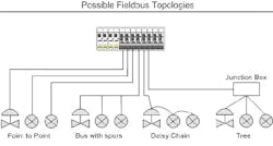
Foundation fieldbus offers several possible network topologies, such as point-to-point, bus-with- spurs, daisy-chain, tree or mixeda combination of all supported topologies (See Figure 2 below).
The trunk is the main communication pathway between devices and is typically the power supply to spurs on the segment. The segment is a section that ends in terminators and cannot exceed 1,900 m in length, including the main trunk and spurs. A spur is a branch off the trunk and can vary in length between 1 m and 120 m.
Production areas at the Boehringer Ingelheim Chemicals plant in Petersburg, Va., are deemed hazardous, requiring an intrinsically safe fieldbus installation.
The physical components of a standard (non-IS) Foundation fieldbus H1 network are a power supply, power conditioner, optional repeater(s), cables, junction box(es), terminators and devices. The power supply provides 19 to 26 VDC to the trunk and must be conditioned using a power conditioner either separate from or integral to the power supply. The power supply can be either bulk or dedicated; however, the power conditioner is not optional. Repeaters can be used to extend a segment, which will allow another 1,900 m. The total number of devices on any segment is 32. The total number of devices on a segment may also be limited by logical components of the fieldbus, such as the scheduled macrocycle, control-system loop configuration and the amount of data communicated to/from a device (links and VCRs).
FIGURE 2: TOPOLOGIES GALOREIndividual shielded, twisted-pair cable defined as Type A cable in the IEC/ISA Physical Layer Standard is preferred. The maximum segment length of 1,900 m will have to be reduced if another type of cable is selected or if cable types are mixed. Table 1 summarizes the maximum lengths of different types of cables.
Junction boxes with terminal blocks are one method for connecting several devices to the segment at a single location, as well as providing an installation point for the segment terminator. Pre-manufactured junction box systems designed for Foundation fieldbus are readily available. A terminator is an impedance-matching device located at both ends of the segment that consists of a 100 Ω resistor in series with a 1 µF capacitor.
TABLE 1
|
Cable Type |
Description |
Size |
Maximum Length |
|
A |
Twisted-pair with shield |
#18 AWG |
1900 meters |
|
B |
Multi-twisted pair with shield |
#22 AWG |
1200 meters |
|
C |
Multi-twisted pair without shield |
#26 AWG |
400 meters |
|
D |
Multi-core without twisted pairs and having an overall shield |
#16 AWG |
200 meters |
Hazardous Area Classifications
A hazardous location is an area where an explosive atmosphere exists due to flammable gases, vapors, liquids, combustible dust or ignitable fibers or flyings. The area classification is determined in accordance with properties of the material creating the potential explosive atmosphere and the possibility that the materials may be present. The North American method of area classification is defined in the National Electrical Code (NEC) for the U.S. and the Canadian Electrical Code for Canada. A typical area classification is Class 1, Division 1, Groups C/D T3C. But what does this classification mean?
The class term separates the fuels into families (Table 2). Class 1, for example, would signify an environment of flammable gases, vapor or liquids.
TABLE 2
|
Explosive Atmosphere Classification | |
|
Class 1 |
Flammable gases, vapor or liquids |
|
Class 2 |
Combustible dusts |
|
Class 3 |
Ignitable fibers and flyings |
|
Reference NEC Chapter 5 - Special Occupancies | |
The division term separates the hazardous area into two parts based on the probability that an explosive fuel and air mixture will be present (Table 3). A Division 1 classification signifies that ignitable concentrations of flammable gases, vapors or liquids can exist all of the time or some of the time under normal operating conditions.
TABLE 3
|
Likelihood of Atmosphere Classification | |
|
Division |
Zone |
|
Division 1 Ignitable concentrations of flammable gases, vapors or liquids can exist all of the time or some of the time under normal operating conditions. |
Zone 0 Ignitable concentrations of flammable gases, Vapors or liquids are present continuously or for long periods of time under normal operating conditions. |
|
Zone 1 Ignitable concentrations of flammable gases, vapors or liquids are likely to exist under normal operating conditions. | |
|
Division 2 Ignitable concentrations of flammable gases, vapors or liquids are not likely to exist under normal operating conditions. |
Zone 2 Ignitable concentrations of flammable gases, vapors or liquids are not likely to exist under normal operating conditions. |
|
Reference NEC Chapter 5 - Special Occupancies | |
The group term separates the division into materials with similar explosive properties (Table 4). Group C/D signifies that the gases, vapors or liquids have similar explosive properties to ethylene and propane.
TABLE 4
|
Group Classification (Ease of Ignition) | |
|
Division 1 and 2 |
Zone 0, 1 and 2 |
|
A Acetylene |
IIC Acetylene and Hydrogen |
|
B Hydrogen | |
|
C Ethylene |
IIB Ethylene |
|
D Propane |
IIA Propane |
|
E Metal Dust |
|
|
F Coal Dust | |
|
G Grain Dust | |
|
Reference NEC Chapter 5 - Special Occupancies | |
Areas can also be classified based on maximum temperature (Table 5). If the maximum operating temperature of a device is greater than 85 ºC (T6), the device must be marked with the proper temperature category. A T3C-rated device has a surface temperature that does not exceed 160 ºC.
TABLE 5
|
Temperature | |
|
Division 1 and 2 |
Zone 0, 1 and 2 |
|
T1 <= 450º C |
T1 <= 450º C |
|
T2 <= 300º C |
T2 <= 300º |
|
T2A <= 280º C, T2B <= 260º C, |
N/A |
|
T3 <= 200º C |
T3 <= 200º C |
|
T3A <= 180º C, T3B <= 165º C, |
N/A |
|
T4 <= 135º C |
T4 <= 135º C |
|
T4A <= 120º C |
N/A |
|
T5 <= 105º C |
T5 <= 105º C |
|
T6 <= 85º C |
T6 <= 85º C |
|
Reference NEC Chapter 5 - Special Occupancies | |
Wiring in a Hazardous Area
Several installation and wiring methods are allowed in a hazardous area. Two of the most common methods are explosion-proof (Ex) and intrinsically safe (IS). Both methods limit the amount of energy that can be released or present in the environment.
Explosion-proof instruments are not immune to explosions. An explosion-proof instrument is designed so that if a vapor were to be ignited inside the instrument enclosure, the enclosure would contain the energy of ignition and disperse it into the classified area at a low enough level to prevent an explosion outside the instrument. Explosion-proof designs require special installation methods, and the instrument needs to be rated explosion-proof for the proper area classification (i.e., Class I, Division I, Groups C/D).
An intrinsically safe (IS) design limits the electrical energy at the instrument to a level below the explosive limits of the area. The explosive limits and the amount of available power for an IS circuit is based on the ignition curves of a given gas or gas family and the related minimum ignition energy. Intriniscally safe designs have less stringent installation methods, such as the ability to use NEMA 4 instead of NEMA 7/9 enclosures and standard wiring methods.
Intrinsic safety is defined by the ISA as a type of protection in which a portion of the electrical system contains only intrinsically safe equipment that is incapable of causing an ignition in the surrounding atmosphere.
An intrinsically safe circuit is defined by the NEC as a circuit in which any spark or any thermal effect is incapable of causing ignition of a mixture of flammable or combustible material in air under prescribed conditions.
An intriniscally safe circuit is defined by CENELEC as a circuit in which no spark or any thermal effect produced in the test conditions prescribed in this standard (which include normal operation and specified fault conditions) is capable of causing ignition of a given explosive atmosphere.
The two IS standards in use today are ia and ib, where safety is maintained with up to two faults or one fault, respectively. The ia standard is acceptable in Zone 0 classifications and ib standard is acceptable in Zone 1, Zone 2, Division I and Division II classifications.
An intrinsically safe design requires a systems approach to implementation because each component can fail, and each component may contribute capacitance and/or inductance to the overall circuit. Some of the details to be mindful of during the design of an IS system are entity parameters for the safety apparatus and instrument; cable inductance and capacitance; grounding; vendor control drawings; and cabinet layout for IS wire routing. You may also need to contact your insurance carrier to discuss your design. In the past, Factory Mutual (FM) required that all IS devices be FM-approved. In most cases this is not a problem, but not all IS devices manufactured today carry FM approval.
Intrinsically Safe Foundation Fieldbus H1
The concept of intrinsically safe systems was developed in the early 1900s as a result of a mine explosion that killed 439 people. In the early days, IS systems were used mainly when there was no other method available. As time progressed, IS systems became an accepted standard in Europe. In 1965, the ISA published RP 12.2 Intrinsically Safe and Non-Incendive Electrical Instruments. In the years following, many standards and approval agencies around the world became more aligned to IS systems (ISA, IEC, NFPA, CENELC, UL, FM, OSHA and many more), allowing North America to take advantage of all of the products being used in Europe.
Intrinsically safe devices or apparatus are approved by either an entity or a system method. The entity method requires that devices be certified individually as an intrinsically safe device or apparatus. It becomes the responsibility of the user to select and integrate the individual components into a system using the devices entity parameters and the vendor control drawing.
The system method requires that the manufacturer combine its individual components into a certified system. The manufacturer must also provide a control drawing that depicts the system, as well as any constraints that would violate the certification/approval, such as maximum cable capacitance and inductance.
The early barriers used in IS fieldbus implementation limited the available bus current to about 80mA per segment. If you use 20 mADC per device as the load, that equates to four devices per segment without taking into account any losses due to barriers or cable lengths. This does not realize a cost savings in comparison to traditional 4-20 mADC IS circuits, nor does it demonstrate any of the benefits of bus technology. To increase the amount of usable bus current and simplify the IS design, an international standard for IS Foundation fieldbus systems was developed and is now known as the Fieldbus Intrinsically Safe COncept (FISCO).
The standard was based on work done by Physikalisch-Technische Bundesanstalt (PTB), the national metrology institute in Germany, and involved theoretical and experimental techniques. The first edition of the standard was published in April 2005 as IEC 60079-27. FISCO simplified the design calculations required in the traditional entity approach by requiring the testing and certification of all fieldbus components to a set of standards defined by the specification.
By certifying the devices to a standard and using cable that falls into the limits of the experimental data (See Table 6 below), the design calculations were simplified to Ohms law and inductance/capacitance entity parameters were no longer components in the calculations.
TABLE 6
|
FISCO Cable Parameter Limits | |
|
Parameter |
Value |
|
Loop resistance |
15 Ω/km to 150 Ω/km |
|
Loop inductance |
0.4 mH/km to 1 mH/km |
|
Loop capacitance |
80 nF/km to 200 nF/km |
|
Maximum spur length |
30 m in IIC and IIB |
|
Maximum total cable length |
1.0 km in IIC and 1.9 km in IIB |
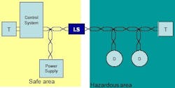
This also allowed FISCO power supplies to generate up to 120 mADC in the IIC (A/B) gas group and 265 mADC in the IIB (C/D) gas group, which equates to perhaps five devices and twelve devices respectively, assuming a 20 mADC load per device and losses due to cable resistance and other factors. Figure 3 depicts a typical FISCO system.
FIGURE 3: WIRED FOR SAFETYGetting Around FISCO Drawbacks
The drawback to the typical entity and FISCO-based IS system is that the barrier is located in the safe area, which is the portion of the fieldbus trunk that sees maximum current flow and equates to a large voltage drop.
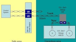
We found an alternative to FISCO in Moore-Hawkes Routemaster entity-based IS system. Route-Master has the benefits of the system method and none of the disadvantages of the entity method. Route-Master systems are based on a split architecture that separates the barrier into two parts (See Figure 4 below).
FIGURE 4: BYPASSING FISCOThe first barrier includes a smaller resistance seen at the interface between the safe and hazardous area (high current position), and the second barrier includes a larger resistance seen at the device coupler located in the hazardous area. This design allows for a smaller voltage drop and 350 mA DC on the trunk, which equates to sixteen devices (assuming 20 mADC load per device).
The device couplers are compatible with FF-816 device entity parameters (Vmax. in = 24V, Imax. in = 250mA, Pmax. in = 1.2W) and can be implemented in Class 1 Division 1 Groups C/D with IS connections for Class 1 Division 1 Groups A/B/C/D, when they are installed per the appropriate control drawing (HCGFB-902). Since each spur has IS current-limiting resistors, each spur an independent IS loop.
This helps to simplify the entity parameter calculations by using worst case scenarios. You can calculate the capacitance of a worst-case spur, which is 120 m of the chosen cable, plus an FF816 device, calculate the L/R ratio for the chosen cable, and document these calculations noting that no current or future spur can be longer than 120 m and no other cable type can used. Each spur has electronic auto-resetting, short-circuit protection that prevents short circuits on one spur causing problems on another spur or the trunk.
Application in the Pharmaceutical Industry
Boehringer Ingelheim Chemicals, Inc. is a bulk active pharmaceutical ingredient manufacturing facility in Petersburg, Va. The facility consists of three primary production buildings that have their interiors classified as hazardous areas (Figure 6). The classification for the buildings is generally Class 1, Divisions 1 and 2 and Groups C/D with a maximum temperature requirement of T3C. Our manufacturing processes are controlled primarily by an Emerson Process Management DeltaV control system.
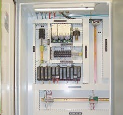
We installed our first IS fieldbus system in the facility in 2001 as part of our Bay 34 Upgrade Project. We implemented an entity IS fieldbus, using barrier/repeaters with a maximum of four devices per segment. Figure 7 is photograph of a cabinet implementing an entity-based IS fieldbus system. This implementation meant our control system cabinets were large and required a large number of fieldbus segments.
We recently installed an automated solvent distribution system in our S1 production building to accurately deliver organic solvents and raw materials for cleaning and production to approximately 125 end-use points. As part of this project, we wanted to install an IS fieldbus infrastructure that would meet our project requirements, as well as provide capacity for future growth. Our S1 production building is four stories tall, divided into 10 vertical production bays and electrical rooms located in the north end of the building.
Our IS fieldbus design needed to meet the following requirements:
- Installation in a Class 1 Division 1 Group C/D area,
- Wiring to instruments in a Class 1 Division 1 Group B/C/D area,
- Optimize control performance and minimize segment-to-segment communications by allowing primary elements and final control elements of a control loop that are physically located on different floors in a bay to be connected to the same segment,
- Maximize the number of devices allowed per segment,
- Run trunk/segment across the full length of the S1 building to reach the north end electrical rooms,
- Be an intrinsically safe system allowing our technicians to troubleshoot and work on the system without needing a hot work permit or having to shut down the process,
- Hot-swappable replaceable components,
- Provide room for future expansion and growth.
After evaluating available technologies, including our existing Bay 34 IS fieldbus, traditional IS fieldbus and FISCO systems, we contacted Chris Peters at Logical Innovations of Richmond, Va., our local MooreHawke representative to inquire about the Route-Master system. After talking with Chris, we learned that the Route-Master system would meet all our design requirements, as well as provide us future growth capabilities. We installed 15 segments with more than 100 instruments operating on the segments.
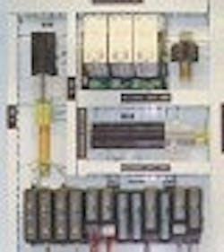
The Route-Master implementation, in conjunction with remote I/O, has allowed us to install four DeltaV controllers in the same amount of cabinet space (See Figure 5) that we originally used to install one controller. Since the installation, we have had no Route-Master component failures and have standardized the fieldbus installations in our facility around the Route-Master system.
By using the Moore-Hawke IS system, BI Chemicals could install four DeltaV controllers in the same space that was originally used for one DeltaV.
Conclusions
Choosing and implementing fieldbus in a hazardous area can be a difficult task. To complicate the matter even further, non-incendive Foundation fieldbus (FNICO Fieldbus Non-Incendive COncept) is gaining popularity, but that is a subject for another article. However, if you keep a few concepts in mind during your decision-making and design process, you can minimize the chance of getting bogged down in all of the complicated specifications and find your way to an optimal solution. I have summarized a few points to consider during your process in Table 7 below. I have also included a number of excellent documents on hazardous-area classification, intrinsic safety and Foundation fieldbus (many of which I referenced while writing this article) in the reference section of this article.
TABLE 7
|
|
ENTITY |
FISCO |
ROUTEMASTER |
|
Control Drawing |
Required |
Not required. List of devices required only. |
Required |
|
ENTITY Calculations |
Required |
Not required as long as you use cable that meets the FISCO specification. Ohms law is required for voltage drop. |
Required but only done once for the worst case scenario of the longest spur and the type of cable you specify. |
|
Maximum Spur Length |
120 meters (likely reduced due to voltage drop and capacitance) |
30 meters |
120 meters |
|
Maximum Segment Length |
1900 meters (likely reduced due to voltage drop and capacitance) |
1900 meters IIB |
1900 meters |
|
Maximum Devices (20 mADC and no losses) |
4 |
5-6 in IIC A/B |
17 |
|
Maximum Current |
80 mADC |
120 mA DC IIC |
350 mA DC |
REFERENCES
- Fieldbus Foundation.
- AG-163, Foundation Fieldbus Application Guide 31.25 kbit/s Intrinsically Safe Systems.
- AG-140, Foundation Fieldbus Application Guide 31.25 kbit/s Wiring and Installation.
- FD-043, Foundation Fieldbus Technical Overview.
- IEC 60079-27, Electrical apparatus for explosive gas atmospheres: Fieldbus intrinsically safe concept (FISCO) and Fieldbus non-incendive concept (FNICO).
- NFPA 70- National Electrical Code (NEC).
- NFPA 497 Recommended Practice for the Classification of Flammable Liquids, Gases or Vapors and of Hazardous (Classified) Locations for Electrical Installations in Chemical Process Area.
- NFPA 499 Recommended Practice for the Classification of Combustible Dusts and of Hazardous (Classified) Locations for Electrical Installations in Chemical Process Areas.
- Factory Mutual, FM Global Property Loss Prevention Data Sheets 5-1, Electrical Equipment in Hazardous (Classified) Locations.
- Factory Mutual, Approval Standard for Intrinsically Safe Apparatus and Associated Apparatus for Use in Class I, I & III, Division 1, and Class I, Zone 0 & 1 Hazardous (Classified) Locations.
- ANSI/ISA-12.01.01-1999, Definitions and Information Pertaining to Electrical Instruments in Hazardous (Classified) Locations.
- ANSI/ISA-RP12.06.01-2003, Recommended Practice for Wiring Methods for Hazardous (Classified) Locations Instrumentation Part 1: Intrinsic Safety.
- ISA-TR12.2-1995, Intrinsically Safe System Assessment Using the ENTITY Concept.
- Moore-Hawke.
| About the Author |
