I am not in favor of the staggering investments in these processes, but if we are going to scrape the bottom of the fossil fuel barrel, at least we should do it safely.
The Overall Process
Once the test wells identify the depths at which the oil/gas bearing zones are located, the operation begins. It consists of three phases: 1) drilling, 2) production and 3) closing or killing the well. (For a description of killing the well, see Phase 3 at the bottom of this article). Looking at the equipment used in this process (Figure 1), this industrial process might appear to be very complex and, therefore, hard to control. In fact it is simple!
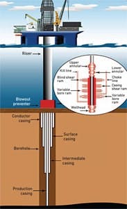
Figure 1. The main components of an offshore oil well and its blow-out preventers (BOP).
The control goal is simply to balance the variable pressure at the bottom of a vertical U-tube with the pressure of a fluid which is circulated in it. The fluid pressure at the bottom of the U-tube is adjusted by changing the pump discharge pressures and by changing the hydrostatic head on the bottom of the U-tube through the adjustment of the density of the circulated fluid.Phase 1—Drilling
Phase 1 starts with drilling the bore hole (~ 36 in. dia.) by lowering a drill bit into the well and rotating it by a shaft inside a vertical drill pipe (~ 6 in. dia.). Through this pipe drilling fluid is pumped down, serving the dual purposes of cooling the bit and carrying up the "cuttings" to the rig, through the annulus (or annular) between the pipe and the bore hole. As the drilling progresses, a number of casings are installed for support, and a number of blow out preventers (BOP) are added, so that if excessive pressure is encountered, the well can be closed.
During Phase 1, the goals are
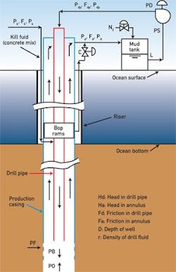
- To keep the flow velocity and pressure at the bottom (PB in Figure 2) high enough to carry the cuttings up. This pressure ranges form 5000 to 10,000 psig.
- To keep the PB higher than the oil/gas pressure (PO) in the formation. This safety margin (ΔP = PB – PO) should be held at about 500 psig.
- To keep the PB pressure by some 500 psig below the pressure (PF) at which the drilling fluid would start to escape into the wall of the borehole by fracturing it (PB < PF – 500 psig).
- To protect against a "blow-out" that can occur if high pressure gas pockets are encountered during drilling.
Pdp ~ PD = PO + ΔP + Fd – Hd
Pa ~ PS = PO + ΔP – Fa – Ha
Once they are accurately measured, all that is needed is to satisfy the relationship:
PF > PB = PO + ΔP
[pullquote]In order to satisfy requirement 4) above, the system also must be able to detect both the developments of "kicks" and initiate the response to them. The development can be detected by noting an increase in the flow from the well (usually Coriolis meters are used to measure the flows — F in Figure 2) by the rise in the level in the "mud tank" (L) and by the rise in the drill pipe and annulus pressures (Pdp and Pa). The critical measurements, therefore, are the pressures, densities and flows as shown in Figure 2.
When a "kick" is detected, the pressure balance must be reestablished by doing the following (in sequence):
- Increase the nitrogen (N2) blanket pressure on the mud tank (Figure 2).
- If that does not stop the "kick", gradually close the variable bore ram (Figure 1) in the BOP and if "soft" closure is desired (no sudden rise in pressure), throttle the choke valve (C in Figure 2) while doing it.
- If the "kick pressure" is still rising, first close the casing ram in the BOP and then (if needed) the blind shear ram (Figure 1).
Phase 2—Production
During the production phase, the pipe that in Phase 1 was taking the drilling fluid down into the well serves to carry the oil or gas up from the formation to the rig. They rise under their own pressures, so normally no pump is needed to provide the driving force. During this phase, the flow direction is reversed, the fluid properties are changed (pressures, flows, densities, conductivity), but the process is similar.
The laws of hydraulics through a vertical U-pipe still describe the process. Therefore, some of the same sensors that were used in Phase 1 can also be used, although they require recalibration and range change.
The oil/gas is collected in storage tanks and is transported by barges or through pipelines under the ocean to the shore. During this phase the required safety controls to protect against "kicks" are similar to those described in Phase 1. The fact that the product is flammable requires additional protection to guarantee safety. If the BOPs failed and the presence of flammables is detected (Chapter 7.8 of Volume 2 of the Instrument Engineers’ Handbook), the immediate response should be to turn off all ignition sources on the rig or start nitrogen purging them. If, in spite of these steps, fire is detected and can not be extinguished, the rig should be disconnected from the well and moved away.
Phase 3--"Killing" the Well
When, for any reason, the well is to be closed ("killed"), killing fluid (usually a concrete mixture) is pumped into the well through the kill line shown in the upper right of Figure 1. As this mix is heavier than the oil, it displaces the oil and plugs the well. In this phase too, until the concrete sets, the maintaining the pressure balance is critical and can be controlled by keeping the mix density high enough to provide the required hydrostatic pressure to prevent blowout. If the concrete is too dilute (low density), a methane kick can blow it out, as occurred at the BP accident.
The key to improving safety during all three phases of the described process is to have reliable (redundant) sensors and fully automatic response to unsafe conditions so that time is not wasted by the need for obtaining management approvals, and mistakes are not made because operators are untrained or panicked. It is also important to keep the operators fully informed of the conditions on the rig. This requires using "smart annunciators," which not only inform them about the existence of unsafe conditions, but also gives them instructions on what to do about them.
