Terry Blevins is a principal technologist at Emerson Process Management and was elected to the Control Process Automation Hall of Fame in 2004. Kurtis Jensen is a field instruments marketing manager at Emerson Process Management.
When using wireless transmitters in control applications, it's necessary to structure the control in a manner that compensates for non-continuous measurement updates. One way to do this is to use the approach called PIDPlus (see "How to use wireless for control," May '15, p. 39). Similarly, when using a wireless valve, the control must be structured to account for variable delays that may be introduced by wireless communications to the valve. Fortunately, technical solutions exist that enable wireless transmitters and/or wireless valves to be successfully used in closed-loop control applications.
Wireless throttling valve is no problem
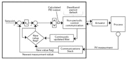
The approach in PIDPlus enables wireless transmitters to be used in closed-loop control for a variety of process applications. Wireless adaptors were recently introduced by manufactures that may be used to change the target position of a digital positioner for a throttling valve. PIDPlus features may be combined with the modifications needed for control using a wireless valve to address any combination of wired and wireless field devices (Figure 1).
Figure 1: Wireless adaptors have been introduced that can change the target position of a digital positioner for a throttling valve, which allow PIDPlus features to be combined with the modifications needed for control using a wireless valve to address any combination of wired and wireless field devices.
If communications to a wireless valve is disrupted, PIDPlus will automatically compensate for this loss. The feedback value of the last target valve position communicated by the wireless valve is used in conjunction with the latest measurement update to create the reset component of PIDPlus.To minimize the power consumed by the valve positioner, the calculated PID output is transmitted to the wireless valve only if the criteria for non-periodic control communications are met. When the time since the last communication to the wireless valve is equal to or greater than the configured period of communication and the communication of the valve acknowledgement to the last change in target position has been received, then a new target position is transmitted to the valve when either or both of the following criteria are met:
- The absolute value of the difference between the calculated PID output and the last target value communicated to the valve exceeds a configured deadband value.
- The time since the last communication to the valve exceeds the configured default reporting time.
The addition of this non-periodic control communications can be incorporated at any point along the control path after the calculated PIDPlus output.
Ideally, the feedback of implied valve position (i.e., the target position that the valve accepted and is working to achieve) would be immediately communicated by the wireless valve back to the control system in the response to the target position write request. However, the communications from the controller to the wireless valve can introduce significant and variable delay in the time the valve acts on a write request and the change in valve position being reflected in the controller. The main sources of delay are:
- Write request processing—the WirelessHART gateway is already engaged in sending an outstanding device change request. Thus, the gateway queues a new write request until the valve has had time to respond to the previous write request.
- Downstream communication—the gateway doesn't schedule downstream communication. Thus, the gateway must hold a write request to the valve until it can send this message.
- Device reply—the device reply to a write request is not scheduled. Thus, there may be significant and variable delay in the communication of a reply to a write request.
To allow the PIDPlus to automatically compensate for this variable delay in wireless communication of the write response, wireless adaptors are improved for use with digital valve positioners. The improvements include the support of a new HART command that may be used to schedule the time at which the wireless valve takes action on a new target value.
WirelessHART command eases control
The new HART command designed for control allows a "time to apply" field to be included with the output value communicated to a wireless valve. This added field specifies a time in the future when the output value takes effect. The time to apply value is selected to ensure that the valve receives the output communication before this future time. Thus, it's possible to calculate the implied valve position based on the target position communicated to the valve and the specified time when the valve takes action on the new target position. The calculated implied valve position will match the target value used in the valve as long as the delay time specified in the command is equal to or greater than the time required to communicate a new target position to the valve.
To ensure that the calculated implied valve position accurately reflects the target position in the valve, a new output command to change valve position should be issued only if confirmation of the last communication has been received. It's important to note that WirelessHART networks are designed to periodically distribute time, and this time value is used in the control system and the wireless network to ensure that all devices have a common sense of time.
The target valve position maintained by the wireless valve may be changed using the new HART command. If the target valve position specified in the command is a different value than that contained in the previous change request issued to the WirelessHART gateway, it's considered to be a new request. If the gateway has received the wireless valve response to the last requested change, it acts on the new change request.
Field trial proves it's practical
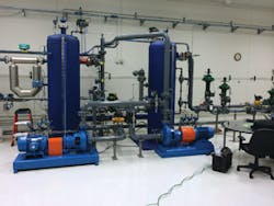
Control of a liquid flow process was tested at Fisher Controls in Marshalltown, Iowa, using a commercial-sized throttling valve, a wireless adaptor and PIDPlus. In these tests, closed-loop flow control was evaluated using both wireless and wired flow measurement. Communications with the wireless valve used a new HART command that allows a "time to apply" to be specified. The PIDPlus external reset input was modified to allow the application of delay to compensate for the time to apply. In addition, non-period communication was used to minimizing valve movement (Figure 2).
Figure 2: Control of a liquid flow process was tested at Fisher Controls in Marshalltown, Iowa, using a commercial-sized throttling valve, a wireless adaptor and PIDPlus. In these tests, closed-loop flow control was evaluated using both wireless and wired flow measurement.
The wireless transmitter used in these tests was configured for an 8-second periodic update. During each test, the integral of absolute error (IAE), total valve travel and communications statistics were calculated. Screen captures of the chart showing the control loop parameters were made after each automated test. The test results can be summarized as follows:- PID tuning was set strictly based on the process gain and dynamics. The fact that the tuning was never changed throughout the wireless test illustrates that the PIDPlus tuning is not impacted by transmitter and valve update rate and delay introduced by communications. Good control was achieved in all wireless valve and wireless transmitter tests using this tuning.
- Using a non-period communications to the valve reduced the number of changes in valve position by a factor of 70, and cut total valve travel by over 50%. Introduction of non-periodic communications to the valve had no impact on loop stability, and had minimal impact on control performance.
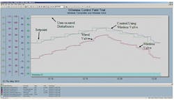
Figure 3: A wireless transmitter and valve can also be used to alter the control response for a change in setpoint. Equally good control performance can be achieved when unmeasured process disturbances are introduced into a flow process.
The tuning of the PID using the wired flow transmitter and wired throttling valve was used without modification in all the wireless control tests. The time to apply was set to 8 seconds in all wireless valve tests. Most commands were received by the valve before the time to apply, but a few arrived late. It shows that communications to the valve have a range of unpredictable arrival times. Equally good control performance was achieved when unmeasured process disturbances were introduced into the flow process (Figure 3).Wireless works for discrete control
A variety of wireless discrete transmitters have been introduced into the process industry that can be used to monitor the state of a process operation. For example, point-level detection can be provided by a wireless liquid level switch. Wireless valve positioners are also available to interface with an on/off pneumatically actuated valve. Such wireless valve positioners can be used in control applications to regulate on-off valves.
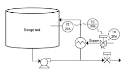
Figure 4: Temperature control can be automated using a wireless temperature transmitter and a wireless on-off valve to regulate the steam used to heat the tank.
Numerous process applications may be addressed by discrete control that uses continuous or discrete wireless transmitters and wireless on-off valves. One example of where wireless discrete control has been successfully applied is in storage tank temperature control. There is often a requirement that storage tanks for plant feedstock or intermediate or final product be maintained at a temperature that is required for pumping or processing (Figure 4).If the mode of the temperature control, TC206, is set to Auto, the discrete output to the wireless on-off steam valve (TV206) is opened when the tank temperature falls below the setpoint (SP) value. When the temperature reaches setpoint, the steam valve is turned off, and remains off until the temperature drops by more than the configured deviation limit. When the temperature drops below setpoint by more than the deviation limit, the steam valve is opened again. When the mode of TC206 is changed to Manual, the operator may manually open and close the steam valve.
Other examples of where discrete wireless control has been installed in operating plants are documented in The Engineer's Guide to Industrial Wireless Measurement, 2014 Edition.
For more information on control using wireless transmitters, see Chapters 6-7 of Wireless Control Foundation—Continuous and Discrete Control for the Process Industry. Workshops in the book highlight key points. In addition, YouTube videos showing workshop solutions are referenced at the book's website at www.wirelesscontrolfoundation.com. The book may be purchased through the www.ISA.org website and at Amazon.com.
References
- Blevins, T, "Improving PID Control with UnreliableCommunications," proceedings of ISA Expo 2006, Houston.
- Blevins, T, Briggs, S, Jensen, K, "Using Wireless Throttling Valves in Column Control," session at Emerson Exchange 2014, Dallas.
- Delfosse, N, "AkzoNobel on its Wireless Network at a Belgium Plant" CHEManager International, May 11, 2011.
- The Engineer's Guide to Industrial Wireless Measurement, 2014 Edition, publication number 00805-0100-1039, rev. AA, January 2014.

Leaders relevant to this article:


