Béla Lipták defines 5 levels of process control
Manual Control (Figure 1): Manual feedback control is performed by the operator by watching the hot water temperature and manually throttling the steam flow to keep this outlet temperature constant. Manual feedforward control is performed when the steam flow is throttled on the basis of the temperature and flow of the incoming cold water.
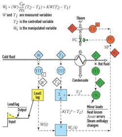
Feedback Control (green components in Figure 2) is similar to manual control, except that the operator is replaced by an automatic controller, which is more accurate and does not get tired or distracted, and its "personality" is tuned to match that of the controlled process. By "personality" I refer to the dynamics (gain, time constant, dead time) of the process.
Manual feedforward and feedback control depend on the operator to control the process.
Figure 2 illustrates the case when the control valve is on the steam side of the heater. If it is on the condensate side, a smaller valve can be used, but the dynamics of the process will be slower and non-symmetrical, because lowering the condensate level is much faster than building it up. On the other hand, this configuration eliminates the minimum condensing pressure problems that can interfere with the steam trap operation at low loads.
While feedback control is the most commonly used, it has serious limitations. The main one is that it cannot anticipate and, therefore, cannot prevent errors because it can initiate corrective action only after an error has developed. Therefore, in the case of the liquid heater process, if either the properties of the manipulated variable (for example, steam pressure) or the load (cold fluid flow or temperature) change, feedback control will wait until these changes upset the outlet temperature before initiating corrective action.
Cascade Control (red components in Figure 2) can correct for manipulated variable upsets, such as steam pressure changes, before they could upset the controlled variable (temperature). As shown in Figure 2, the cascade loop consist of two controllers in series, but has only a single setpoint, that of the primary (master) controller, the TIC. The main value of having a secondary (slave) controller (the FIC shown in red) is that it will act as the first line of defense against steam quality disturbances, preventing these upsets from entering and upsetting the primary controlled variable (temperature).
More advanced systems replace the operating person with an automatic controller capable of handling the personality of the process.
For the cascade slave loop (FIC) to be effective, it should be more responsive (faster) than the master. Some rules of thumb suggest that the slave time constant should be less than 1/4 to 1/10 that of the master loop, and the slave’s period of oscillation should be less than 1/2 to 1/3 of the master loop. In case of the steam heater process, this requirement is usually satisfied.One should also be careful to prevent "reset wind-up" in the primary controller (TIC). This can occur because the TIC is usually provided with an integral mode, which keeps integrating the error as long as it exists and, therefore, if the FIC setpoint is blocked (such as when it is switched to manual) it keeps integrating until its output saturates (reaches maximum), and when the FIC is returned to automatic control, a large upset occurs. To guarantee "bumpless transfer," provide "external reset," which is an internal logic component in the TIC algorithm that deactivates the integral mode if the TIC output does not equal the FIC measurement, and reactivates it only when it does.
So cascade takes care of correcting for disturbances caused by changes in the manipulated variable, but what about load changes?
Feedforward Control (blue components in Figure 2) can correct for load changes, which in the case of a heater, can be variations in the flow rate or in the temperature of the entering cold fluid. The required total steam flow (Ws) is the product of the required temperature rise (T2-T1), the flow rate of the cold fluid (W) and the ratio (K = Cp/Hs), which is the ratio of the specific heat of the fluid (Cp) and the latent heat of the steam (Hs). Because this calculation is never completely accurate due to heat losses in the system and measurement errors, it has to be corrected by the feedback TIC’s output signal (T2*) in the feedforward calculation. This way, because the feedforward correction is on the outlet of the cascade master, the TIC does not even know if the incoming flow or temperature has changed.
Feedforward provides a more direct solution than does feedback alone. On the other hand, the feedforward system consists of several devices if implemented in hardware, or several blocks of software if implemented digitally. The function of these blocks is to implement the mathematical model of the process. Unfortunately, the use of feedforward control is limited to the better understood processes because when the process is more complex than a heat or mass transfer process, the feedforward calculation (or the required measurements), becomes complicated or even impossible.
Another limitation of feedforward is that a load change can temporarily change the load itself, for which feedforward cannot correct.
Lead/Lag Control (yellow component in Figure 2) is needed if load changes cause a temporarily increase or decrease in the load. In case of the liquid heater, for example, if the load (flow W) increases, initially an additional load will appear, because in order for the heat exchanger to transfer more heat (through its fixed heat transfer area), its own temperaure must also increase. This need to heat the metal body represents a temporary additional load, which will drop to zero when the required higher temperature is reached. We refer to this phenomenon as "lead" action. Similarly, when the load drops, the heat exchanger itself can be cooler and while cooling, this heat also serves to heat the cold fluid, so the load will appear to be temporarily reduced ("lag" action).
In addition to the listed control techniques, the tool box of the automation engineer contains many other, more sophisticated techniques to control more complex or multivariable processes, such as when the load variables cannot be directly measured or when they are unpredictable (See Optimization of Industrial Unit Processes), but the most often used techniques are the five I have discussed.


