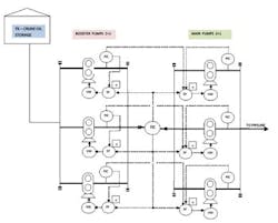
The pumping station delivers crude oil to the pipe line, and has two pumping stages, booster and main (each one in a redundant configuration—two operative and one cold standby—with a total capacity of 300 KBPD). All pumps (both boosters and mains) are of the positive displacement type. The boosters are 1200 hp and the mains are 3000 hp each. Each pump has its own hydrodynamic speed driver for velocity control whose setpoint is provided by a selector control between the total flow and the discharge pressure for the booster pumps. For the main pumps, the selector is between the total flow, the suction pressure and the discharge pressure, and, therefore, the controller with the lowest demand will set the velocity to the respective pump. Our questions are as follows:
- For a pumping configuration with reciprocating pumps in series, each one with its own speed control, is it possible to maintain an accurate and stable pressure control just using speed control?
- If a booster pump or a main pump shuts down, would this control system be able to respond in time in order to maintain pressure balance on the system?
- Someone suggested to us to include a control pressure valve to recirculate oil at the intermediate manifold between boosting stage and main stage, which will fast-actuate in order to stabilize the pressure if needed. Would this work?
We appreciate your suggestions and critique. There is too much debate here at my company about this point.
Luis Fernando Betancur
[email protected]
A: You are right, Chapter 8.34 in Vol. 2 does not answer all your questins, you also have to read Chapters 7.4 and 8.35 to get the full picture.
Your solution of using variable-speed (VS) positive displacement (PD) pumps, instead of throttling bypass control valves, is the correct one, because the pipeline process is a mostly friction one, and you would be wasting a lot of energy in the form of valve pressure drops. With PD pumps, cavitation also is less of a problem.
As to installing a recirculating control valve back to the supply tank from the intermediate manifold, this is reasonable if you want to mix the tank contents before start-up (to reduce settling and achieve uniform density) or to gradually increase the booster discharge pressure during start-up to the required inlet pressure of the main pumps before they are started, but not for normal operation. The relief valves should take care of overpressures. You need those plus blocks and check valves on each pump. In addition to the pressure safety valve (PSV) opening in the bypass, the booster pumps have to shut down any time the main pump trips, and, similarly, the main pumps have to trip to prevent the development of low suction pressure, when the boosters trip.
I assume you have selected the booster pumps that require a minimum inlet pressure (net positive suction head required, NPSHR) that is lower than the net positive suction head available (NPSHA). To determine this minimum, you determine NPSHA using the minimum possible supply tank level and oil density in combination with the maximum oil density expected.
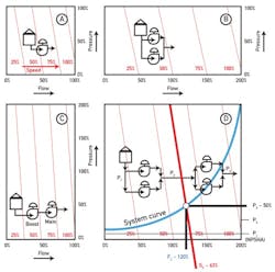
The purpose of the booster pump is to keep the main pump suction pressure constant by compensating for supply tank level, viscosity, etc. If we understand "the personality"of the pipeline process, the required controls become fairly obvious. As you can see in Part A of Figure 1, the pump curves (in red) of all VS-PD pumps are very steep parallel lines, because flow changes very little, even with large changes in discharge pressure. If you have a pair of pumps in parallel, pump flows are added (Part B), and if you have a pair of pumps in series, pump pressure is added (ΔPs are added in Part C). In your case, you have both series and parallel operations (Part D), so the combined pump curves are as shown by the parallel red lines. For sake of this illustration, I have assumed that all pumps are the same (which obviously is not the case), but it simplifies the explanation.
Because your process is a "mostly friction" one, with only a small elevation ("static head") component, your system curve is basically a parabola (blue in Part D). If you select an operating point on Part D by controlling the discharge pressure (or flow) at a particular value, you have, in effect, also set the other. For example, in the sketch, I have picked a flow controller (FIC) setpoint which equals 120% of the full capacity of one pump. This automatically sets the discharge pressure also P3 = 50% of one pump) and the speed at 63%.
Obviously, in your actual configuration the four pumps are not the same, (the main pumps are nearly three times as powerful as the boosters) and, consequently, the combined pump curves will be different from the ones I have shown in Part D, but the concept is the same.
Now, let me turn to the control of the the pumping station. If you want only stable operation, you can modulate the speed of the booster stage to maintain the suction pressure for the main stage, and can throttle the speed of the main stage to keep the discharge (flow or pressure) constant. This, with safety limits and start-up/shutdown logic is all you need.
What I will describe below is the system you should consider if you want to maximize the efficiency (minimize the energy consumption) of the pumping station. To do that, we have to understand that this process has four degrees of freedom (total load, boost/main load ratio, and load distribution in both pairs of pumps) and, therefore, we can place four controllers on it without causing excessive interaction ("fighting") among them. Also, because the oil is incompressible, the loops are fast, so I usually tune these loops for mostly integral behavior (very little proportional gain).
The first loop controls the discharge pressure of the main stage. I usually use a "neutral gap" PIC, so that the controller output remains unchanged as long as the pressure is within ±1% of setpoint. This stabilizes the loop, which has fast measurements, but relatively slow speed controller response, and is, therefore, noisy or interacts with other loops.
The second loop controls the load distribution between the boost and main stages (booster % = (P2-P1)/(P3-P1)) to guaranty maximum station efficiency. This interstage (booster discharge) pressure controller compares the above optimum desired setpoint with the actual value of (P2-P1)/(P3-P1), and adjusts the load on the booster stage until it is optimum. Naturally, this PIC setpoint is limited (high selector), so that it can not drop below the minimum suction pressure requirement of the main stage.
Similarly, we can optimize the other two loops by optimizing the distribution of the flows among the two pumps within each stage. This is accomplished by measuring the individual flows, and because we know the optimum flow distribution (optimum setpoint = F1/(F1 + F2), we can modulate the speeds to achieve that. In this configuration, the output of the stage pressure controller becomes the cascade master of the more efficient pump's flow controller, while the less efficient meets the remaining load.
To implement his type of optimized control system, the pump supplier has to provide reliable efficiency data for the pumps. If they can't do that, or if the unique piping configuration of the particular pumping station is to be also considered, efficiency data can be accumulated on the basis of past operating performance. This is done by comparing the kWs that were needed to deliver the same flows at the same ΔP at different pump loading combinations in the past, and selecting the least energy-demanding one. This strategy can also be used to signal the need for "pigging" (cleaning) the pipeline if the pumping power required to deliver the same load rises.
Such an optimizated variable-speed pumping station can reduce the energy cost of operation to one half of a constant- speed pumping station using control valves.
Béla Lipták
[email protected]
A: This is fundamental cascade control. Control of the booster pump is the inner loop, compensating for such things as tank level, suction pressure, etc. The goal of the booster pump is to provide a constant input to the main pump.
Victor Wegelin
[email protected]
A: The issue of pump control has several aspects that require analysis.
- Is the booster pump receiving from an extremely low head pressure and raising the outlet pressure so that the main pump can supply the outlet pressure within the correct pump curve?
- Will the booster pump be in line with one or several main pumps, such that the booster pump(s) can deliver the required flow and pressure to the main pump(s)?
- If the booster is not dedicated to one single main pump, but rather to several, it may need the analysis of how many booster pumps you need to have.
- Since the premise is that the pumps are reciprocating, which means that the speed control and response time of the pumps are not instantaneous, the time delay of operating the booster and main pumps has to be linked based on time delays, as well as production needs.
Based on the basics defined before, we would be able to define the control requires as follows:
Assuming that the booster is dedicated to one main pump, the most effective method is that the speed of the motors be regulated and have dedicated bypass valves to avoid cavitation surges and overpressuring the system.
You can operate the system with two individual pressure control loops, or you can have a cascade loop with a master and slave controller arrangement. The main issue is to define the actual time delay of pump responses and ramp-up speeds (to avoid the surges and cavitation). Obviously the final arrangement will depend on the detailed configuration of the system.
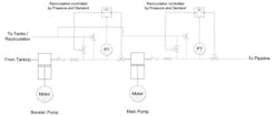
The basic control scheme is presented below.
It must be noted that for clarity's sake all the pressure gauges, switches, flow elements, etc., are not shown—just the basic concept of an option to control the pump arrangement.
This system allows the ramp-up of speed and control of the recirculation, minimizing cavitation, surges or overpressuring the system.
If there are several booster(s) that feed several main line pumps, the basic control would need to include flow measurement for better distribution and probably ratio control for the dosification of the pressures and flows to minimize upsets.
To best develop the required control scheme, more detailed information is required. This is only a basic scheme.
Alejandro Varga
[email protected]
A: Unlike centrifugal pumps, the torque requirements of PD pumps are directly related to the DP across the pumps and independent of speed. Hence, a pressure-based speed control will accurately maintain stable flow across the pumps with good turn down as long as you maintain net positive inlet pressure (NPIP) requirements of both the pumps (minimum pressure limit based on current process fluid density in your control loops).
Since PD pumps cannot run on shut head, you need to shut off booster pumps any time the main pump trips along with a PSV in the booster bypass loop. Similarly the main pump will trip on NPIP protection when the booster trips.
A bypass control valve on booster pump is used when speed control is not implemented due to cost or pump design or electrical supply system harmonics limitations.
L. Rajagopalan
[email protected]
A: Rules of thumb for series pump start-up/control are mentioned below.
NPSH is maintained prior to start of the second pumps.
Second pump will not run dry.
Capacity of both pumps will be adjusted and similar, unless second pump operates on the pressure controlled manifold.
Pressure control valve on the discharge line.
Debasis Guha
[email protected]
A: Assuming that crude oil is incompressible, a buffer tank will be required between the pumps to absorb the variations as the pistons reciprocate. The first pump should be controlled by the level in the tank. The second pump should be controlled by whatever it pumps into. But I am a simple mechanical engineer with no experience in crude things, and I can't afford a copy of the IEH.
Bill Hawkins
[email protected]
A: I have never set up such a system, but have a couple comments. First, it might be interesting to measure the constant-speed case total recirculation flow to enable some efficiency optimization, similar to the variable-speed case. Second, I like the variable-speed method too, but wonder if the cost (vs fixed speed) would be justifiable at the large HP mentioned.
Al Pawlowski
