This column is moderated by Béla Lipták , automation and safety consultant, who is also the editor of the Instrument and Automation Engineers’ Handbook (IAEH). If you have automation related questions send them to: [email protected]. Read other Ask the Experts columns.
- What is the maximum number of taps that can be placed on an orifice flange?
- I have an orifice flow element and want to connect two differential pressure (DP) transmitters to it, one to serve basic process control system (BPCS); the other, the emergency shutdown safety instrumented system (SIS). Is there any problem with doing this?
- Please also advise if I can connect two DP transmitters to the same orifice flange, using them to provide a SIS system with backup (1oo2). Is there any problem with doing this?
M. Ulaganathan
[email protected]
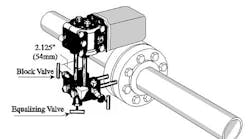
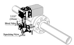
Figure 1: Adding a second differential pressure transmitter and sharing the orifice flow element between safety instrumented function (SIF) and basic process control system (BPCS) control loops can be considered if the fluid is clean or if two separate sets of pressure taps are provided on the two sides of the orifice flange, so that the pressure taps of the two transmitters are not shared.
A1: Before answering your specific question, let me make some general observations about sharing the same instrument to serve both normal operation and safety control systems. In this area, SIS standards are confusing and often contradictory. IEC 61511-1, clause 11.2.4 states that the BPCS shall be separate and independent from the SIS to “the extent that” the functional integrity of the SIS is not compromised.
The qualification “to the extent that” destroys the clarity of this requirement and allows for the interpretation that the standard does not always require physical separation. Yet another clause (clause 9.5.2) does seem to require such separation “unless the failure rate is sufficiently small.”
Again, this qualification adds further ambiguity, as it assumes that the failure rate is known, when in most cases it is not. So what is the user to do? Well, we users should understand that such vagueness is not necessarily accidental, but is intended to allow the user to reduce costs. This is unfortunate because in high risk life-safety applications, cost should not be a factor. Therefore, in such cases, override safety control (OSC) should be used instead of SIS.
Now, coming to your specific question, SIS does not give clear-cut rules on component sharing. As you will see from the answers, some experts interpret SIS as allowing the sharing of both the pressure taps and the DP transmitter. Others feel that only the sharing of the pressure taps is allowed, while still others interpret SIS as if it allows the sharing of only the orifice and requires separate taps and transmitters. Remember that these are the answers of highly experienced process control experts.
SIS says that components can be shared as long as the sharing cannot interfere with the proper operation of the safety instrumented function (SIF) loop. This suggests that it is up to the user to decide if a component can or can not be shared. (One might ask: What is the value of a standard that does not tell you what to do?) So how does one make sure that sharing “will not interfere” with the proper operation of the SIF loop? One interpretation is to look at the proposed control system and ask: Will the SIF be able to shut down the process even if the BPCS failed? If the answer is yes (using this interpretation), sharing is allowed.
Because in your case if the BPCS transmitter (Figure 1) were shared and it failed, the SIS would not be able to shut down the process, one should add another DP transmitter on the other side of the orifice flange to serve the SIS loop. Some might consider this as providing 1oo2 backup. Yet, as you will see from the answers that follow, different expert users will reach different conclusions.
My own recommendation (regardless how people interpret SIS) is that, if the process fluid is clean and the pressure taps are not shared, so that mechanical damage or plugging of the lead line connecting the BPCS transmitter cannot affect the operation of the SIF transmitter, the sharing of the orifice plate is OK.
On the other hand, if the process is a critical one and life-safety is involved, overrule safety control (OSC), where no sharing of even the sensing element is allowed, should be applied because damage to the orifice plate itself would affect both loops. Therefore, in that case I would use complete separation, such as using a Coriolis meter in addition to the orifice.
Béla Lipták
[email protected]
See Also: SIS: Standards By Committee
A2: This is a prime example of what you were talking about in the article [Lessons Learned, Nov. 2014, http://www.controlglobal.com/articles/2014/sis-standards-by-committee/]. The standard is so unwieldy it makes finding answers to any question regarding basic design an epic search. It is interesting that I spoke to three SIS experts in my office and received three slightly different answers and interpretations.
Yours, Béla, was an excellent article. I actually work in the safety instrumented system field and I must say you make many very valid points. I have sat in on this committee and many of the working groups and I think they have lost their way to a degree. There is so much bickering regarding the terminology that the actual reason for the group's existence seems to fade away. The standard in its current form to me seems like we are putting new windshield wipers on a smashed windshield. There is a great deal of thought and pseudo-quantitative reasoning going on, and I am not sure how much value is actually being added to the industry aside from the publicity it garners.
My interpretation is that per IEC 61511-1 (which is pretty much ISA 84) clause 11.2.4, the BPCS shall be designed to be separate and independent to the extent that the functional integrity of the SIS is not compromised. This to me means that there are no hard and fast rules stating that things cannot be shared as long as the relationship does not allow for a deleterious effect on the SIS. I have always interpreted this to mean that if the BPCS went offline, the SIS should be able to bring the process down.
Honestly, the question presented is a good one. Everyone I spoke to seemed to agree that the sharing of the orifice plate itself was not an issue. The idea of shared taps, on the other hand, caused some debate. The final consensus was that the taps should be separate, though admittedly there are many processes out there that do not do it this way. There was some discussion regarding the use of diagnostics and detection methods to help determine if there is a plugged line.
Michael R. Thompson
[email protected]
A3: You can certainly do as you have proposed, but do not expect the flow readings to ever be the same. Flange taps and pipe taps will always produce different differential pressure readings at the same flow. The “ideal” tap location would be at the vena contracta, which is the point of maximum velocity, but that place changes with the flow rate. The orifice flange tap is always located before the vena contracta, but a pipe tap may be either before or after it, and may or may not produce the same differential pressure as do the flange taps.
Process safety is not a religion. It is technically possible to use the same 4-20 mA analog transmission signal from one transmitter to supply information to both a BPCS and a SIS. Each system would have its own 250-ohm dropping resistor in the same 4-20 mA circuit. Be sure that these two systems are wired in series with each other; you cannot just wire them in parallel, which would be the same as wiring with a single 125-ohm resistor.
Dick Caro
[email protected]
A4: There are orifice plates with more than a single tap (as no one would put in multiple orifice plates). This is common practice when using more than one sensor, one to the control system, one to the safety system. If you wanted both to the safety system and voted them 1oo2, that would also be acceptable (but you would have twice as many nuisance trips).
Paul Gruhn,
[email protected]
A5: There are several things to consider: Common cause, history, maintainability.
Any time there is a common component, the failure rate of the common component needs to be sufficiently small as to not affect the overall functional safety. Clause 9.5 of IEC 61511 identifies assessment of common cause. This holds true whether the elements are redundant, part of two independent protection layers (IPL), or between the initiating cause and an IPL. As a general rule, in clean service where the failure rate of the process connection is significantly low, sharing is acceptable. As the severity of the process connection increases, the impact of the common cause needs to be addressed through diversity, independence or diagnostics. To judge the severity of the process connection, it is helpful to have some process history to justify using common elements. Some instrument manufacturers provide process tap plugging diagnostics, which can be configured to alarm the operator when plugging is occurring. This would help identify the common cause before it impacts the functional safety.
From a maintenance perspective, there needs to be the ability to isolate each sensor separately. The other aspect that needs to be considered is if there will be online maintenance of the SIS device. Clause 11.3 identifies the need to provide compensating measures when disabling a function. Where the compensating measure involves an alarm in the BPCS, the alarm is to be treated as part of the SIS. From a practical point of view, putting more than two taps on a flange is problematic. Isolation valves should be so installed in the impulse lines as to allow for maintenance of each element independently. Also, the isolation valves need to be so managed as to prevent disabling of both devices inadvertently.
Kevin Klein
[email protected]
A6: Generally, you should use one tapping point per instrument, but if the flow medium is fairly clean, and there is good maintenance in the plant, then you can connect several transmitters to the same tap. But in that case, remember that if the impulse line is damaged, it will affect all the transmitters, and the same will occur if the impulse line is plugged.
In sharing loop components, the risk is that if the primary element or impulse lines are fouled, broken or otherwise damaged, all your readings will be affected, and the plant safety will be compromised. The same is true to the voting logic configuration (1oo2).
Alexandro Varga
[email protected]
A7: There is no limitation of taking multiple taps on orifice flanges (flange tap) as long as space allows. However, in case of smaller lines, ensure that there will be sufficient space for accessing isolation valves or manifolds. Therefore, you should not place isolation valves in same plane.
You can definitely share a flow element between SIS and BPCS. There is no restriction on orifice sharing or on using the same orifice in a 1oo2 voting configuration. However, 1oo2 voting should be avoided as it will increase spurious trips, though safety integrity will be highest.
Lastly, why do you want to use two different taps (flange and pipe) for the same element? Pipe taps are used for larger diameter elements, and you should try to avoid them. A flange tap is good enough.
D. Guha
[email protected]

Leaders relevant to this article:


