"When an automated sequence was triggered, operators often didn't know why the plant had moved away from normal operation." Tessenderlo Kerley's Josh Disckson on the company's rationale for using Siemens' Logic Matrix to manage and visualize interlocks.
The actions of regulatory control loops within a distributed control system (DCS) environment often make a certain intuitive sense. Valves open and close in response to process disturbances, striving to keep flow rates, temperatures and pressures at their designated setpoints. But the typical DCS is also called on to enforce a range of logical relationships whose operations are often less clear.
These process interlocks, permissives and automated sequences are often intended to maintain production or protect equipment from damage, whether in response to a process excursion or the actions of a well-meaning but ill-advised human operator. A simple permissive, for example, might prevent starting a pump unless its suction valve is open. Similarly, a simple interlock might shut down the pump in response to its suction valve being closed. And, in an example of a simple automated sequence, a high fluid level sensed in the tank immediately downstream might cause that same pump to stop.
Such nuanced logic is often embedded in function-block code, making configuration tasks complex and clouding operators’ understanding of the underlying logic at work. Until recently, such was the case at agricultural and industrial chemicals manufacturer Tessenderlo Kerley, Inc., (TKI) where a central team of Phoenix-based engineers remotely support operations at nine different manufacturing facilities across the United States.
The way things were
The company relies on Siemens’ SIMATIC PCS 7 at its production facilities, but the way in which the organization had used interlock blocks to implement automated sequences and related logic wasn’t well documented nor easy to follow, according to Josh Dickson, lead process control engineer.
“When an automated sequence was triggered, operators often didn’t know why the plant had moved away from normal operation,” Dickson said. A phone call to Phoenix for engineering support soon followed.
What the company needed was a better way to visualize the interlock logic at work in its plants, with the goal of increased operator situational awareness—and fewer phone calls back to engineering, Dickson said. Enter Logic Matrix, a software tool for users of PCS 7 that is designed to clearly communicate interlock parameters, dependencies and current status in an intuitive matrix format. Dickson related lessons learned in the ongoing roll-out of Logic Matrix to TKI’s U.S. manufacturing fleet in a presentation at the 2019 Siemens Automation Summit.
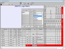
The SIMATIC Logic Matrix arrays interlock causes (x-axis) and effects (y-axis) on a single screen, together with interlock status. The arrows associated with each cause and effect conveniently link directly to the relevant faceplate displays.
Unified, intuitive view
With Logic Matrix, interlock functions are parameterized in an editor according to causes and effects (image). Engineers, operators, planners and inspectors gain a standardized view and common understanding of all interlock functions—without diving into code.
Furthermore, Logic Matrix seamlessly integrates into the PCS 7 operations console. Process-relevant events and alarms are transmitted to the operator system and integrated in the message system. Operators can click back and forth between the Logic Matrix and relevant faceplates. At the same time, all interdependencies with other measuring points are clearly depicted.
“Logic Matrix gives us the ability to display all interlocks and automated sequences on a single page,” Dickson said. “Setpoints and trip points are all visible on the HMI.”
Dickson has found the software easy to configure, and noted that the editor is free and included with PCS 7 starting with version 8.2. Logic Matrix does, however, consume Process Objects (Siemens’ tag-count licensing scheme), and a Logic Matrix Viewer license is required for each console.
Dickson cautioned that if effects are deleted from the Logic Matrix, those remaining are automatically renumbered. “Be careful, as the automatic renumbering of effects could cause a blip resulting in a shutdown.” Dickson also noted that the background colors for active interlocks (red in the image accompanying this article) are configurable. “This is powerful, because we would like to redo the configuration so that automated sequences and interlocks are not displayed together in the same matrix,” Dickson said. “If automated sequences are displayed separately, then I can use a different color for them that isn’t as alarming as red.”
Tessenderlo Kerley has begun rolling out Logic Matrix to the company’s other U.S. production sites, and the process has proved “faster and easier than we thought,” Dickson said. “We can install Logic Matrix, then delete the old logic after the fact.”
Plus, he has more time on his hands, now that the operators who already have Logic Matrix aren’t calling quite so often.


