Under the hood of override control
By Harold L. Wade, Ph.D., Wade AssociatesLIVE TO override. Override to live. While the old motorcycle mantra can be adapted for the process industries, override control refers to applications where one process variable controls the process in normal operation, but during abnormal operation another variable assumes control to prevent encroachment on safety, process or equipment limits. A key element of override control, or selector control, is a hardware or software-based selector function, which selects the lower or higher of two or more controller outputs for passage to the final actuator. When applying override control to a fired heater (See Figure 1 below), the heater outlet temperature normally controls the process. Excessive tube heat causes its temperature controller overrides to prevent encroachment of the tubes high limit. If the non-selected controller contains reset action, it will tend to windup unless special provisions are made. FIGURE 1: OVERRIDE CONTROL BASICS
Heater outlet temperature normally controls the process in a fired heater, but excessive tube heat causes its temperature controller overrides to prevent encroachment of the tubes high limit. (Click the figure to view an enlarged .pdf.)
OVERRIDE control was developed in the days of pneumatic controllers. Reset action was achieved by connecting the controller output to the reset bellows, forming a positive feedback loop within the controller. Override control took advantage of this architecture by connecting the output of the selector switch to the reset bellows of both controllers (See Figure 2 below). With this configuration, the selected controller acted as a normal proportional-plus-integral (PI) controller, and the non-selected controller was prevented from winding up. The feedback from the selector output to the controllers is variously called reset feedback, external reset, and external reset feedback.FIGURE 2: OVERRIDE WITH PNEUMATICS
OVERRIDE control was developed in the days of pneumatic controllers. Reset action was achieved by connecting the controller output to the reset bellows, forming a positive feedback loop within the controller. Override control took advantage of this architecture by connecting the output of the selector switch to the reset bellows of both controllers (See Figure 2 below). With this configuration, the selected controller acted as a normal proportional-plus-integral (PI) controller, and the non-selected controller was prevented from winding up. The feedback from the selector output to the controllers is variously called reset feedback, external reset, and external reset feedback.FIGURE 2: OVERRIDE WITH PNEUMATICS
Based on pneumatic architectures, override control connects the output of the selector switch to the reset bellows of both controllers. The selected controller acts as a normal proportional-plus-integral (PI) controller, and the non-selected controller is prevented from winding up. (Click the figure to view an enlarged .pdf.)
DCS, PLC Implementation
With digital technology, several techniques are used by manufacturers to prevent windup of the non-selected controller. These techniques fall into three main categories: reset feedback, forced initialization, and output tracking.Reset feedback essentially mimics the action of the traditional pneumatic controllers (See Figure 3 below). The selector output is connected to the input of unity-gain first order lags in each controller. The time constants are the reset times of the controllers. The first order lags are the mathematical counterparts of the reset bellows and needle valves of the pneumatic controllers shown in Figure 2.FIGURE 3: OVERRIDE WITH PI CONTROLLERS WITH RESET
In reset feedback, the selector output is connected to the input of unity-gain first order lags in each controller. The time constants are the reset times of the controllers. (Click the figure to view an enlarged .pdf.)
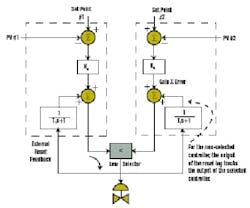
ASSUME THAT the left-hand controllers output is selected. Since its output is connected (through the selector) to the reset feedback, it is acting as a normal PI controller. The output of the right-hand controller is the product of its gain-times-error plus the output of the first-order-lag. At steady state, the output of the first-order lag is equal to its input; at other times the first-order-lag output will lag its input. Note that the non-selected controller in Figure 4 below does not wind up.Except for set point changes, the output of both controllers will only change gradually. Therefore, there will never be a bump in the output of the selector device. If the PV of the non-selected controller begins to approach its set point, its output will approach that of the selected controller. At equality, the crossover point is reached. Any further encroachment on the limit will cause a graceful reversal of the roles of the selected and non-selected controller.Similarly, in forced initialization, the output of the selected controller is connected to the reset feedback port of the both controllers. Logic in the selection device detects which is the non-selected controller. For the non-selected controller, this reset feedback immediately passes through (or bypasses) the first order lag (See Figure 4 below). Hence, the output of the non-selected controller is always the output of the selected controller, plus its own gain-times-error.FIGURE 4: FORCED INITIALIZATION OVERRIDE
ASSUME THAT the left-hand controllers output is selected. Since its output is connected (through the selector) to the reset feedback, it is acting as a normal PI controller. The output of the right-hand controller is the product of its gain-times-error plus the output of the first-order-lag. At steady state, the output of the first-order lag is equal to its input; at other times the first-order-lag output will lag its input. Note that the non-selected controller in Figure 4 below does not wind up.Except for set point changes, the output of both controllers will only change gradually. Therefore, there will never be a bump in the output of the selector device. If the PV of the non-selected controller begins to approach its set point, its output will approach that of the selected controller. At equality, the crossover point is reached. Any further encroachment on the limit will cause a graceful reversal of the roles of the selected and non-selected controller.Similarly, in forced initialization, the output of the selected controller is connected to the reset feedback port of the both controllers. Logic in the selection device detects which is the non-selected controller. For the non-selected controller, this reset feedback immediately passes through (or bypasses) the first order lag (See Figure 4 below). Hence, the output of the non-selected controller is always the output of the selected controller, plus its own gain-times-error.FIGURE 4: FORCED INITIALIZATION OVERRIDE
For the non-selected controller, reset feedback passes through (or bypasses) the first order lag, so the output of the non-selected controller is always the output of the selected controller, plus its own gain-times-error. (Click the figure to view an enlarged .pdf.)
AGAIN, WITH traditional implementation, there is never a jump in either controller output due to switchover. With the forced initialization, however, at the time of switchover, there may be a jump in the output of the non-selected controller, depending on the magnitude of its error. A jump away from the other controller output is of no consequence. If the jump is in the other direction, however, it can again override the other controller and move the valve to an unwarranted position.[Editors note: Part 2 of this article will cover forced initialization under adverse conditions, output tracking, and other methods of implementation, including selection based on error and override control using Foundation fieldbus. For more information, read: Wade, Harold. L., Basic and Advanced Regulatory ControlSystem Design and Application, Second Edition, ISA, Research Triangle Park, NC, 2004; or Foundation Specification: Function Block Application Process, Document FF-891, Part 2, the Fieldbus Foundation, Austin, TX.]
Harold Wade, Ph.D., is President of Wade Associates, a Houston-based consulting firm, and is a longtime member of CONTROL's Automation Hall of Fame.
AGAIN, WITH traditional implementation, there is never a jump in either controller output due to switchover. With the forced initialization, however, at the time of switchover, there may be a jump in the output of the non-selected controller, depending on the magnitude of its error. A jump away from the other controller output is of no consequence. If the jump is in the other direction, however, it can again override the other controller and move the valve to an unwarranted position.[Editors note: Part 2 of this article will cover forced initialization under adverse conditions, output tracking, and other methods of implementation, including selection based on error and override control using Foundation fieldbus. For more information, read: Wade, Harold. L., Basic and Advanced Regulatory ControlSystem Design and Application, Second Edition, ISA, Research Triangle Park, NC, 2004; or Foundation Specification: Function Block Application Process, Document FF-891, Part 2, the Fieldbus Foundation, Austin, TX.]
| About the Author |
