1660601665285 Ct1812cvrstryleadart3

Basics of PID in 25 points

Learn the Best Practices for PID

  • Measure each flow, inventory (e.g., level or weight and pressure), every process variable for safe operation and environmental protection, and each indicator of process efficiency and capacity (e.g., composition, quality, pH, and temperature) with sufficient accuracy (particularly least drift and best repeatability), speed and rangeability.
  • Manipulate each flow by a control valve or variable-frequency drive (VFD) with the least deadband (e.g., < 0.4% backlash) and sufficient linearity (e.g., < 5:1 gain change), resolution (e.g., < 0.2% stiction), speed (e.g., < 2-sec., 86% response time) and rangeability (e.g., > 40:1).
  • Make sure every component in the process, whether a reactant, inert, byproduct or product, is accounted for by field or scheduled lab measurements, and is controlled to ensure exit or consumption by reaction with no continual accumulation.
  • Pair controlled variables (e.g., composition and temperature) with manipulated variables (e.g., flows) that have the largest effect as seen in Relative Gain Array (RGA).
  • If the RGA assessment of choices doesn't clearly favor a particular pairing, choose the manipulated and controlled variable pair with the smallest deadtime-to-time constant ratio.
  • Use flow feedforward for gas pressure control with linearization of valve characteristics.
  • Use flow ratio control for composition, level and pH control, where there's a secondary flow controller and a ratio controller (RC) with a setpoint and bias that both can both be remotely set or manually adjusted by the operator. If the RC block doesn't have a remotely settable bias, the RC output becomes the input to a bias and gain block.
  • Ratio control (RC) details:
    1. Connect BKCAL_OUT from a manipulated RC setpoint or bias to BKCAL_IN of the PID, correcting the RC to ensure a bumpless transfer to the remote setting of the RC setpoint or bias.
    2. The RC input is the leader flow (e.g., largest feed). The RC output is the cascade setpoint of the secondary flow controller, or is the input to a bias and gain station whose output becomes the cascade setpoint of the secondary flow controller. 
    3. For vessels and columns, the primary controller corrects the RC bias. 
    4. For inline plug flow systems, the primary controller corrects the RC setpoint.
    5. For reactants, there may be several flow loops ratioed to the leader flow (e.g., primary reactant flow). To eliminate temporary stoichiometric imbalances from changes in production rate, put a setpoint filter with a filter time on each flow loop just large enough for a smooth response, so reactant feed flows move in concert.
  • For override control of constraints (e.g., maximum pressure, temperature, or throttle valve position), use external-reset feedback to intelligently prevent unwanted integral action; tune each PID gain to provide the correct point of takeover (selection) of the override PID relative to its setpoint; historize the total time each PID is selected; and capture the overshoot of the setpoint. 
  • Use cascade control to: 
    1. Provide rapid correction of secondary upsets and nonlinearities (e.g., secondary flow loop correction for pressure changes and installed flow characteristic). 
    2. Enable flow ratio control by manipulating a flow PID setpoint instead of a valve. 
    3. Give a relatively constant and easily estimated open-loop process gain from controller output (CO) scale needed to prevent violating the low PID gain limit for processes with a near-integrating, true integrating or runaway response. 
    4. Convert the secondary time constant from a detrimental term in the primary loop creating deadtime to a beneficial terms as the largest time constant in the secondary loop, thus decreasing the deadtime-to-time constant ratios of both loops, and offering tighter control. 
    5. Reduce the deadtime and hence the ultimate period of the primary PID, enabling better handling of disturbances originating in the primary loop by more aggressive tuning. 
  • Match the PID output limits and engineering units to the setpoint limits and engineering units of the secondary loop. Set any anti-reset windup (ARW) limits to match the output limits, except for special cases where you set the ARW limits inside the output limits when the PID must move quickly through stiction at a low limit, or quickly recover from a high limit that's an adverse operating condition. 
  • Use valve position control (VPC) to maximize feed rate, waste fuel and waste reagent use, and minimize energy usage by minimizing compressor pressure and maximizing the refrigeration unit or cooling tower temperature by forcing affected control valves (e.g., feed, waster fuel or reagent, coolant, steam and vent valves) to the maximum throttle position. 
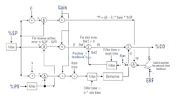
  • Use positive-feedback implementation of integral action (Figure 2) for the ISA Standard form to provide true external-reset feedback (e.g., dynamic reset limit). 
  • ISA standard form with true external-reset feedback

    Figure 2: All signals are percent-of-scale in the PID algorithm but inputs and outputs are in engineering units. For structures with no P action, gain is zero for the proportional mode. Gain is one for the integral mode, and equal to the PID block gain setting for derivative mode. Bias is used as input to the reset time filter block when there is no integral action. Bias is the PID output when the error is zero, and is filtered by the reset time whose best setting is reduced to be about the deadtime. External-reset feedback (ERF) is, for example, secondary loop process variable (%PVs) or fast valve readback. 

  • Use external-reset feedback with setpoint rate limits to provide directional move suppression to enable a VPC to provide a gradual, smooth optimization and fast getaway for abnormal conditions, and to prevent unnecessary crossings of the split-range point. 
  • Use external-reset feedback to stop oscillations from deadband and stiction, a slow secondary loop, or slow control valve, and to provide enhanced PID action to prevent oscillations for increases in analyzer cycle time. 
  • Use signal characterization of the controlled variable for pH titration curves and of the manipulated variable for installed flow characteristic, where the changes in process gain or valve gain, respectively, from changes in slope are greater than a factor of five. 
  • Minimize total loop deadtime by faster and more precise measurements and valves, shorter transportation delays, faster fluid velocity and better mixing. 
  • Minimize process noise by a sensor location that's less affected by cross-sectional changes in velocity, phases, temperature and concentration. 
  • Use middle-signal selection to prevent adverse reactions to a single sensor failure of any type, decrease reaction to noise or a slow sensor, reduce unnecessary maintenance, increase reliability and accuracy, improve diagnostics, minimize lifecycle costs, and maximize onstream time and product quality. 
  • Choose loop objectives and choose the PID structure in the ISA Standard Form by turning off modes and by setting setpoint weights and tuning the PID accordingly. Since there's no interaction in the time domain like there is in the Series Form to prevent derivative action from exceeding integral action, the rate time must not exceed one-fourth the rest time. 
  • Employ procedure automation and state-based control to utilize the best operator and process knowledge to eliminate any operator manual actions during startup, transitions and recovery from abnormal situations, such as equipment and instrument failures or unusually bad disturbances. 
  • Compute a future value of PV by passing the PV through a deadtime block and adding to the block input the change in PV during the block deadtime, that is, the block input minus the block output. Block deadtime is greater than loop deadtime for a good signal-to-noise ratio. Use the future PV value for a faster startup and batch cycle time, where the manipulated flow is initially maximized and then set to its final resting value when the future value is projected to reach a setpoint or batch endpoint.
  • To prevent snowballing buildup of recovered and recycled component concentration, ensure there's a flow controller with a fixed setpoint for a given production rate somewhere in the flow path from the discharge back as a feed input of the affected equipment (e.g., centrifuge, column, crystallizer, evaporator, reactor).
  • Performance metrics should be put online and historized for key unit operations and the production unit. The ratio of total raw material or utility used to total product produced over a representative time (e.g., last 12 hours or last batch) gives a measure of process efficiency. The total product produced over this time gives a measure of process capacity. The total value of product in dollars in this time frame minus the total cost of raw materials (e.g., reactants, reagents, additives and feeds from other units), utilities (e.g., steam, coolant and electricity) and fixed costs (e.g., staff and depreciation) is the profit in dollars. Most important is the trend and not the accuracy of prices and costs. 
  • Use a virtual plant (digital twin) for flexible and fast exploring, discovering, prototyping, testing, justifying, deploying, testing, training, commissioning, maintaining, troubleshooting, auditing and continuous improvement, showing the "before" and "after" benefits of solutions from online metrics.
  • Gregory K. McMillan, Control columnist and Hall of Fame member, can be reached at [email protected], and P. Hunter Vegas, engineering manager, Wunderlich-Malec Engineering, can be reached at [email protected].

    About the Author

    Greg McMillan | Columnist

    Greg K. McMillan captures the wisdom of talented leaders in process control and adds his perspective based on more than 50 years of experience, cartoons by Ted Williams and Top 10 lists.

    Sponsored Recommendations

    Make Effortless HMI and PLC Modifications from Anywhere

    The tiny EZminiWiFi is a godsend for the plant maintenance engineers who need to make a minor modification to the HMI program or, for that matter, the PLC program. It's very easy...

    The Benefits of Using American-Made Automation Products

    Discover the benefits of American-made automation products, including stable pricing, faster delivery, and innovative features tailored to real-world applications. With superior...

    50 Years of Automation Innovation and What to Expect Next

    Over the past 50 years, the automation technology landscape has changed dramatically, but many of the underlying industry needs remain unchanged. To learn more about what’s changed...

    Manufacturing Marvels Highlights Why EZAutomation Is a Force to Be Reckoned With

    Watch EZAutomation's recent feature on the popular FOX Network series "Manufacturing Marvels" and discover what makes them a force to be reckoned with in industrial automation...