Controller algorithms and tuning determines the performance of all control loops, and automation system dynamics set the ultimate process performance by the deadtime, lags, backlash, stiction, rate limiting and nonlinearities introduced. The good news is this is all within our job responsibilities, and simulation can readily provide the knowledge needed and open minds to the possibilities. Seeing a “before” and “after” trend chart can enable process control improvements to be universally recognized and appreciated.
Most of the deeper knowledge I gained in my career resulted from simulations often quite small and focused on a particular unit operation or type of process response. It all started almost 40 years ago with a dynamic compressor model that allowed me to visualize bizarre, 0.03-second jumps into and out of surge—the type of process performance you only want to experience in a simulation. (Especially in this particular case, where surge cycles could damage a multimillion dollar rotor with millions of dollars in profit per day at stake. Incredibly fast valves, measurements, controllers and special algorithms proved essential.)
Greg Shinskey’s great accomplishments as highlighted in the Control article “Greatest source of control knowledge” often stemmed from simulations showing the effect of tuning; options such as external-reset feedback, batch preload and deadtime compensation; and dynamics such as valve backlash and stiction and controller execution time and signal filter. Most of the key players on the ISA 5.9 Standards and Practices committee for a technical report on PID Algorithms and Performance—including Peter Morgan, Sigifredo Nino, Jacques Smuts and Harold Wade—have used simulation to explore and confirm ideas.
10 overlooked details
Today, process engineers responsible for equipment design often tend too much toward a steady-state mindset, neglecting the dynamic simulations needed for process control understanding and improvement. Among the details often overlooked:
- Nonlinearity of control valve and variable frequency drive (VFD) installed flow characteristic as affected by valve inherent flow characteristic and valve-to-system pressure-drop ratio and VFD inverter drive type and static-pressure-to-system-pressure-drop ratio.
- Valve and VFD deadband, resolution limit and velocity limit as determined by valve actuator, positioner, stem and shaft connections, packing, seal, and seat and I/O card and VFD inverter settings.
- Measurement rangeability as largely determined by sensor type and operating conditions, which for flow, in particular, is based on maximum and minimum velocity associated with meter size.
- Dramatic effects of thermowell design and fit on temperature sensor response as well as electrode fouling and aging on pH sensor response.
- Sensor response as a function of distance, velocity, profile and vulnerability to changes in phase affecting transportation delay, lags, noise and representation of actual process variable.
- Transmitter update rate, damping setting, analyzer cycle time and multiplex time.
- I/O scan time plus module and controller execution rate and latency.
- The many possible locations of signal filters including I/O, analog block and PID block.
- PID Standard Form and use of percentage signals in PID algorithm, whereas most publications show PID Parallel Form and PID algorithm with signals in engineering units.
- Location of disturbance entry into loop that's normally an input to the process (termed load disturbance), rather than on the output of process, contrary to what's shown in many publications.
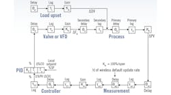
Figure 1 shows the many sources of delays, lags and nonlinearities in a control loop. Not shown are the deadband, resolution limit and velocity limiting that exist in valves and VFDs. The time it takes a controller output to get through the deadband or resolution limit is additional deadtime. A portion of all lags smaller than the largest lag, which is hopefully the primary process lag to slow down load disturbances, become effectively deadtime in a first order approximation. The smaller the size of a lag relative to the largest lag, the greater the portion that becomes deadtime. The ultimate limit to the peak error and integrated error is proportional to the deadtime and deadtime squared.
Nonlinear sensitivities
Additionally, the effect of an operating point nonlinearity seen in all temperature and composition systems, and particularly pH systems, is reduced by a decrease in deadtime since it reduces the excursion of the operating point from the setpoint if the controller is tuned to take advantage of the smaller deadtime. I learned how critical this is for pH, where the slope of the titration curve and hence the process gain can change by orders of magnitude. I needed to make sure I had short reagent injection delays into the neutralizer, short transportation delays to electrodes in recirculation lines, and fast electrodes besides good mixing. Reagent injected in a recirculation line had a much shorter injection delay than reagent added to a dip tube because injection volume is much smaller from control valve located at recirculation line connection. An electrode inserted into the vessel had a slower response and greater propensity for fouling due to much smaller velocity in the vessel compared to recirculation line. Simulations can show these counterintuitive solutions.
Furthermore, Figure 1 reminds us that open loop gain is the product of the valve or VFD gain, process gain and measurement gain, which is 100% divided by measurement span since the PID algorithm works with percent signals. The valve or VFD gain is the change in flow divided by the change in % PID output, which is the slope of the installed flow characteristic for small changes in PID output. For large changes, you need to take the difference in flow between the two points on the installed flow characteristic.
The same situation holds true for process nonlinearities. The process gain is only proportional to the slope of the titration curve for small changes, and gets altered by the difference in pH on the curve for large changes. Hence, the size of a step change will reveal a different valve or VFD gain or process gain, and small step changes are needed to identify a flow characteristic or titration curve.
A side note that is critical for titration curve simulation is that small amounts of carbonic acid are in almost all solutions simply due to absorption of carbon dioxide from exposure to air, reducing changes in process gain across the measurement scale for strong acids and strong bases from six to two orders of magnitude. Simulations must include carbonic acid and any conjugate salts to match laboratory titration curves.
Don’t settle for sluggish tuning
You can prove anything you want, like how great your algorithm is or how unimportant are system dynamics such as wireless update rate, signal filtering or scan time by simply using much more conservative (nice name for sluggish) tuning settings, and putting the disturbance on the process output. This is often not a deliberate deception, and is simply the result of a missing understanding of the consequences. A controller that's detuned is effectively like having tuned a controller for a much larger deadtime. Putting the disturbance on the process output eliminates the benefit seen from a well-tuned PID for lag-dominant processes, where the primary process lag slows down input disturbances and enables a larger PID gain.
The following simple equation derived from Shinskey’s work shows that the integrated error (Ei) for an open loop error (Eo) from a step load disturbance is proportional to the reset time (Ti) and inversely proportional to the controller gain (Kc):
Additionally, the effect of scan time (Ts) and signal filter (τf) time constant diminish as the reset time is increased. Tuning methods that have the reset time equal to the primary process lag for processes, where this lag is greater than four times the deadtime, show less of an effect of scan time and filter time. To avoid this, integrating-process rather than self-regulating-process tuning rules are used for these near-integrating processes, so the reset time is a function of deadtime.
The simulation of a process control loop must include signal characterizers for piecewise linear fit of installed flow characteristics and blocks that you can write parameter settings to for modeling deadtime, lag, rate limiting, deadband and resolution limit anywhere in the loop. The controller must have the same algorithm and features, including anti-reset windup, tracking, feedforward and external-reset feedback as the controller used in the plant. This is best done by a digital twin where the actual controller configuration used in plant can be imported into and exported out of the digital twin that houses the simulation.
You can start with a simulation of the process that's simply a process gain, primary and secondary lag and deadtime—possibly identified by tuning software—to gain a fundamental understanding of challenges and possible improvements. If you want to identify and demonstrate the actual cause-and-effect relationships and dynamics in the process and metrics for improvements, you need first-principle dynamic models of the process that include the ordinary differential equations for material and energy balances, physical properties and the charge balance for pH. The effect of mixing and transportation delays must also be added.
Neural networks and partial-least-squares models can identify inputs that were not known to be important. However, one must realize these are correlations, and may not be valid cause-and-effect relationships. Also, note that these models rely on synchronization of inputs with process outputs, so they can be particularly difficult for continuous models that extend past a single unit operation.
While this can represent a considerable investment of time (that you may need to make on your own, like I did with my first compressor model and the many models for the articles and books I have written, the payoff in what you and your control system can accomplish has incredible long-term benefits.
Please, let’s go beyond doing copy jobs, and seek to use the largely untapped capability of improving automation system dynamics, and take advantage of the many PID controller features. Make the investment to advance yourself and the profession.
Further reading
- “Bioreactor control breakthroughs: biopharma industry turns to advanced measurements, simulation, and modeling,” Control, February 2020.
- “Simulation breeds innovation,” Control Talk, Control, November 2019.
- “Compressor surge control: deeper understanding, simulation can eliminate instabilities,” Control, October 2018.
- “Virtual plant virtuosity,” Control, August 2017.
- “Improve pH control,” Chemical Processing, March 2016.
- “Valve response: truth or consequences,” Control, March 2016.
- “Simulation benefits in mineral processing,” Control Talk, Control, October 2015.
- “Virtual plant provides real insights,” Chemical Processing, October 2008.


