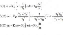
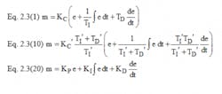
I am a Instrumentation engineer from India. For the past 10 years, I have referred to your Instrument and Automation Engineers’ Handbook, also known as "the bible for instrumentation" in India. I have a problem in understanding PID controllers. My questions are about interacting, non-interacting and parallel PID configurations. I am not able to understand the P, I andD gain terms of the three configurations. In your second volume of the Handbook, 4th edition, chapter 2.3 on control modes—PID variations (pages 124-129), I do not understand:
1) Here in non-interacting form, the proportional gain Kc is getting multiplied with integral and derivative time, giving rise to reset and derivative gain. So how are they non-interacting, since Kp is influencing I & D coefficients?
2) In the parallel form section of the same chapter, you have written that it is also called "independent gain," but have calculated Ki = Kc/Ti and Kd = Kc/Td. They both depend on Kc, so how are they independent? You have also written here that "Ki is in units of time inverse" but if Ki = Kc/Ti, then the unit becomes "Reset/min" and not "min inverse.
3) What is the purpose of a setpoint filter in case of setpoint-softening?
In this same section, you wrote that the advantage of a parallel controller is that the integral-only mode can be achieved by setting Kc = Kd = 0. Now if we go by Ki = Kc/Ti, then for Kc = 0, Ki also = 0, which nulls your previous statement of I-only control.
All of these has led me to believe that there is a mistake in writing/printing the parameters kc, ki and Kd in the section on parallel form in chapter 2.3. Kindly throw light on the above doubts.
Sayan Dey Chaudhuri, Scientific Officer- D / Nuclear Fuels Group, Bhabha Atomic Research Centre
----------
A: The PID-related language and terminology differed between the various industries and changed during the past decade. Because some of the old plants are still using pneumatic or analog electronic controllers, in the 4th edition of Volume 2 of the Instrument Enginners' Handbook (IEH), I have covered all the PID variations. Therefore, in your questions 1) and 2), you are right, some of the names and terms used are confusing and inaccurate. This will be further elaborated on by my expert colleagues below.
For the benefit of the readers who do not have the 4th edition of the IEH, these are the equations your question refers to:
----------
A: Your thinking is absolutely correct. The modes of the PID algorithm are incorrectly named due to a century of tradition, and the many years of dependence upon pneumatic controllers. The PID algorithm originated in servo mechanism theory as applied to machine position and velocity control. This form of servo control has not been burdened with implementation by pneumatic mechanisms and has always used the “independent” or parallel form of the PID algorithm in which each gain factor is applied to each of the three terms independently. This was easy to accomplish in electrical circuits, and remains the form of PID used in machine control, rocket thrust vector control, and rotating equipment speed control.
However, when PID was applied to process control, it was not then possible (prior to the invention of the transistor) to use electronics in the field due to explosive hazards, so it became necessary to use pneumatic computing powered by compressed instrument air. The first pneumatic controllers accomplished PID by using an overall gain factor which they called “Proportional Band,” and an integral term with a Ki term to compensate for proportional offset error. They called this integral term a “reset” of the constant that results from initialization of a proportional controller – hence the term “reset” and the form of the tuning constant to be resets/minute. Later, mechanical engineers invented the derivative term and simply added its result to the reset term. For many years, the algorithm implemented in pneumatic control was called the “independent” form of the PID – incorrectly, but it was tradition.
Over the years, tuning methods were developed by Ziegler/Nichols and Cohen/Coons based on the use of these pneumatic controllers. Later, analog electronic, digital electronic, and microprocessor digital electronic controllers were created for process control and had the choice of implementing the traditional form of PID, or the parallel form of the PID. All of the PLC suppliers have implemented the parallel form of PID, and some of them have implemented the traditional form to allow process control use. All of the DCS vendors have implemented the traditional form of PID. Why? Because of the long tradition in loop tuning developed using only the traditional form of the algorithm.
In my own work to control processes in the pulp and paper industry, I have tried both forms of the PID equation and have observed small differences, but in my judgement, the differences are insignificant. Users of older PLCs for process control, where only the parallel form was offered, have never expressed any dissatisfaction traceable to the PID algorithm, and have used the Ziegler/Nichols and Cohen/Coons tuning methods successfully.
Yes, there is a difference, but not significant. Yes, there is a tradition of misnaming. What Béla calls the “independent” form of PID, I call “traditional.” The other “dependent” form I call “parallel.” I teach the ISA course to prepare control engineers for the ISA Automation Professional Certification examination, and I have removed references to dependent and independent from my course notes.
Richard H. Caro, ISA Life Fellow, CEO, CMC Associates
----------
A: The terminology for PID and its variations has evolved from its origins. It has evolved in separate ways 1) according to regional or community customs, and 2) as vendors have independently produced and termed innovations. Further, the viewpoint with which a user looks at one algorithm depends on the version in which that user has been grounded. Accordingly, there are seeming contradictions in the terminology.
For example, the term parallel could refer to the independent gains form contrasting it to the standard form, or it could refer to the standard form contrasting it with the rate-before-reset form. Also, as an example, I grew up with the term setpoint, but it seems to have evolved back into separate words of set point. [Not here in Control –Ed.]
And, depending on the person’s origins, one name for a configuration might be preferred over another. What I prefer to call the standard form, others prefer to call non-interacting. Some object to the use of the term “standard”, because no organization has labeled it the “standard”, and because some companies are grounded in the interacting form as the product first choice. Alternately, I don’t like labeling something by what it is not, or making it seem inferior to the interacting version.
However, regardless of one person’s preferences and grounding, there are many active classification nomenclatures in practice, and the user needs to be aware of them.
Yes, your observation 1 is correct. In the standard form the controller gain multiplies each term, and you could say that the integral action depends on the gain. However, if you take the viewpoint that Kc is the entire controller gain, not just the proportional gain, then the language conflict disappears.
In the parallel form, gains independently multiply each of the three functions. Yes, again to your finding 2, if you are converting tuning coefficients from the standard form to the independent gains form, then the integral multiplier, KI is equal to the quotient of the controller gain and integral time. In that view it is not independent. But, in the parallel gains form if you change the proportional gain, it does not change the integral contribution of the controller. Also in your point 2 you question the units. Yes, if the CV and MV are in engineering units, then the units on KI are not simply inverse time. However, if the CV and MV are both in %-of-full scale, and the engineering custom that ignores the % basis and considers %MV/%CV to be dimensionless, then the chapter is correct. Finally, in that question, is the issue of turning off the integral action. In the standard form setting tau-I to zero creates a divide by zero. To turn off the integral action, one must set tau-I to infinity.
On Point 3, a good number of users want the controller to aggressively regulate, to rapidly recover from disturbances. These are usually smallish MV moves. However, if an operator makes a set point change, then an aggressive controller will make very large changes in the MV. This may undesirably upset other users on a common utility line, cause rapid temperature changes that stress equipment, or propagate large oscillations downstream. Further, a step change in the set point creates a derivative spike and a proportional bump. Accordingly, many users don’t want the controller response to a set point to cause upsets. Set point softening in any of many methods to temper the impact of a step change in the set point. The set point filter could simply be a first-order lag from the current set point to the target value. However, a lead-lag filter permits a bit of an initial bump depending on the user’s value for lambda.
R. Russell Rhinehart / Emeritus Professor, School of Chemical Engineering
----------
A: Setpoint filter is the mechanism used in PI or PID to reconcile the setpoint and load disturbance responses of an optimally tuned controller, so that the process variable does not overshoot following a step change in the setpoint. Different DCS and PLC manufacturers use diverse ways to introduce a filter to the setpoint. Even a simple ramp may resolve your problem.
Interacting and non-interacting PID controllers also are applied in different ways, and it varies from manufacturer to manufacturer. At the end of the day, using one or another should not be an issue as long as you are consistent with what you are doing.
It would be much easier to give you a better answer by identifying your PID controller algorithm and/or manufacturer of your process control system. Otherwise the explanation may only contribute to obscure the matter even more.
Sigifredo Nino / Summa Control Solutions Inc.
----------
A: I am one of the authors of the Section 2.3, the subject of your questions. With all due respect, my first piece of advice is to become quite familiar with the three forms of PID and their behavior, without becoming concerned with the nomenclature used. Please read the second paragraph following Eq 2.3(2), especially the last sentence, which states, "Since there is no standard terminology among manufacturers, the user is cautioned to examine the mathematical expressions representing the particular form, rather than relying on the manufacturer's nomenclature.” The three forms are given by the three equations in the first answer, Form 1 in Eq. 2.3(1); Form 2 in Eq. 2.3(10); and Form 3 in Eq. 2.3(20).
Also consider the historical context in which the PID has developed. As early as the late 1700s, mechanical mechanisms were developed for regulating certain process, such as for controlling windmill speed, governing steam engines, and controlling hydraulic pump speed. Today we recognize these mechanisms as embodying the "proportional" mode of control.
Skipping many steps of the history, in the first third of the 19th century, several manufacturers developed pneumatic mechanisms consisting of bellows, springs, bourdon tubes, and flapper-nozzles (the error detector) for commercial controllers. If these mechanisms are analyzed, they can be related generally to one of the three forms of PID listed above. But in all likelihood, the working mechanism came before the mathematical description. And the mechanism used was what the manufacturer found to be the easiest to produce. Foxboro's (now part of Schneider Electric) pneumatic mechanism resembled Form 1; Honeywell's pneumatic mechanism generally resembled Form 2; Bailey Controls (now part of ABB) pneumatic mechanism generally resembled Form 3.
Note also, that the terms "non-interacting, interacting and independent gains" did not come about until even later (approximately the latter half of the 19th century) when academic textbooks on process control began to appear in large numbers. And there was not a consistent use of the nomenclature.
Now, to your questions. On question 1, the terms non-interacting and interacting are intended to refer to interaction (or lack of interaction) between the integral and derivative modes only; it does not imply that the controller gain, Kc, has no effect on the integral or the derivative modes.
Examine Eq. 2.3(1) or Fig. 2.3a. Both the equation and the figure show that changes to Ti will have no effect on the response of the derivative mode, and changes to Td will have no effect on the response of the integral mode. Hence, there is no interaction between tuning changes for the integral and derivative modes. That's why this form is called the non-interactive form.
Now examine Eq. 2.3(10) or Fig. 2.3b, and Eqs. 2.3(11), 2.3(12), and 2.3(13). These latter equations show that the effective gain Kc, effective integral time Ti, and effective derivative time Td are all determined by combination of the tuning values, Kc', Ti' and Td'. Hence, there is interaction between the response of the various modes to changes in a tuning parameter. That's why this form is called the interactive form.
On question 2, this form of PID is tuned with proportional gain, KP, integral gain, KI, and derivative gain KD. Changing any one of these parameters will not have any effect on responseof the other two modes. Hence, for a lack of better terminology, this form is called "independent gains." Some authors (and perhaps some vendors) refer to this as "non-interactive." It is true that there is no interaction between the modes, but to use the term "non-interactive" for this form confuses the terminology used with the first form. Therefore I (and most authors) prefer to use the most commonly used terminology and call this "independent gains."
By the way, at one time this form was primarily used for power generation, whereas the both the interactive form and non-interactive form were used in the chemical (e.g., refining, chemicals, etc.) industry. I don't know of a technological reason for this; I think it was probably due more to tradition.
With the advances in technology from pneumatic-analog-controllers to electronic-analog-controllers to digital controllers (i.e, DCS and PLC), most manufacturers have offered two or three of the these forms as options. This is so users who upgraded to a newer technology could still use an option that was most familiar to their technicians.
The paragraph beneath Eq 2.3(23) contains a typographical error. It should read “…can be obtained simply by setting KP and KD to zero."
On question 3 about setpoint filtering, the 1/2 decay ratio, which was the target of 1960s-era Ziegler/Nichols tuning, often produced an overshoot of 30% or greater. Today, this is not recognized as good tuning. It is generally recognized that with any of the forms of PID, if is tuned to give an acceptable response on a setpoint change (such as no more than 5-10% overshoot), the acceptable response to a setpoint change may result in a unacceptable response to a disturbance (an unacceptable response being either too much deviation from setpoint immediately following the disturbance, or a deviation that lasts too long). Conversely, tuning for an acceptable response to a disturbance will likely result in an unacceptable response to a setpoint change.
Placing a filter on the setpoint, as described in Eq 2.3(25), gives an additional tuning parameter, shown in this equation as λ, and has the effect of providing two controllers, one to respond to setpoint changes, and the other to response to disturbances. With this, you can get acceptable tuning for both setpoint changes and disturbances. The paragraph beneath Eq 2.3(27) mentions values of λ of 0.4 or 0.5. My recent experience has shown that a value of λ = 0.65 (+/- 0.1) is probably satisfactory in most cases. In my opinion, this technique of setpoint filtering (called "setpoint weighting" by some manufacturers, and "two-degree-of-freedom control algorithm" by other manufacturers) is one of the most important advances in PID control in perhaps over 100 years. Yet, as far as I know, there is very little knowledge of it, and even less usage, by control system users.
(My book published by ISA, Basic and Advanced Regulatory Control: System Design and Application, 3rd Ed., is currently at the printer and should be shipping by mid-May. It discusses many of the topics mentioned here, including setpoint weighting, in more detail.

Leaders relevant to this article:


