66759ed253a6a831f8eac00b Deadtime Compensation Opportunities And Realities

Deadtime compensation opportunities and realities

June 21, 2024
The benefits of implementing controller integral action by using filtered, positive feedback
Deadtime compensation can be simply implemented by adding deadtime to the external reset feedback signal for a controller implementing integral action through filtered positive feedback.
 
The first article in the series “The pitfalls and promise of override strategies” discussed preventing integral windup. In this article, we discuss how adding deadtime to the reset feedback signal improves loop performance when there’s deadtime in the process or when the process response is characterized by an equivalent deadtime and lag. 
 
Deadtime is extremely detrimental and always present in the process industry, with many possible sources that can make its recognition and understanding challenging. The most notable misconceptions include the idea that deadtime compensation eliminates the effect of deadtime, disturbances are on the process output/process variable, the Smith Predictor is the solution, deadtime compensation is best reserved for deadtime dominant processes, and performance improvement requires turning on deadtime compensation. 
 
Deadtime compensation doesn’t reduce the minimum possible peak error and integral absolute error (IAE), which is proportional to the total deadtime and total deadtime squared, respectively, as detailed in ISA-TR5.9-2023. The reduction of errors is the result of using more aggressive tuning. 
 
Disturbances are on the process input, most notably in terms of changes in stream flows, temperature and compositions (load disturbances), and in final control element discontinuities. 
 
Smith Predictors require modeling the open-loop gain and time constant, and a special configuration to restore the process variable and its corresponding setpoint in the operator interface. Furthermore, the performance of the Smith Predictor is typically evaluated for disturbances on the process output/process variable, resulting in optimistic predictions of performance improvement that aren’t matched by the performance seen for unmeasured load disturbances. This fundamental deficiency is particularly problematic for lag-dominant processes. The Smith Predictor’s use on integrating processes requires a risky conversion of the integrating process gain to a process time constant and steady-state gain. 
 
Studies by Greg Shinskey and the authors on deadtime compensation by external reset feedback (ERFB) show that, while the deadtime compensation benefits are smaller and more susceptible to problems for deadtime dominant processes, the benefits for lag-dominant processes are significant. While the reduction in peak error is negligible and the improvement in integrated error quite small for deadtime dominant processes, the improvement in performance and robustness of deadtime compensation by ERFB is impressive for lag-dominant and integrating processes. Composition and temperature control in vessels and columns, which are often critical for process capacity and efficiency, typically have a lag-dominant or integrating response. When the major source of deadtime is a transportation delay, the ERFB deadtime setting can be readily updated based on production rate. The deadtime observed for setpoint changes can be used to adapt the ERFB setting. 
 
Test results in this study show deadtime compensation via ERFB can improve performance for a wide spectrum of processes, and reveals the tuning adjustments needed and robustness observed. Surprisingly, the ability to handle the inevitable changes in process gain is increased. Finally, for any type of deadtime compensation, it’s important to realize the benefit isn’t seen until the controller is retuned. The ERFB method of deadtime compensation is much simpler to implement, adjust and adapt, and the performance and robustness is much better for what are often more important processes.
 

Controller

 
The controller used in this study is shown schematically in Figure 1. It might be noted that the output limits, other than the high and low limit being specified (100% and 0%, respectively) require no additional logic to prevent integral windup, and this is a benefit of this particular implementation of integral action.

Process model

For a self-regulating process, the process is modeled as a deadtime followed by a lag. For convenience, the loop gain is assumed to be unity. The load disturbance is inserted between the deadtime and lag, though it could be equally represented as a disturbance applied to the controller output with no change in response except delaying the timing of the change in process variable (PV). In each case, the load disturbance is 10% applied at 10 sec. The practice of applying the disturbance on the PV is often adopted by academics, but has no practical value except to replicate a transmitter failure. It gives a false measure of loop performance with respect to peak change in process variable for an unmeasured load disturbance. For an integrating process, the load is disturbed from the initial steady state (50%) to 60% at 10 seconds.

Self-regulating process—lag dominant

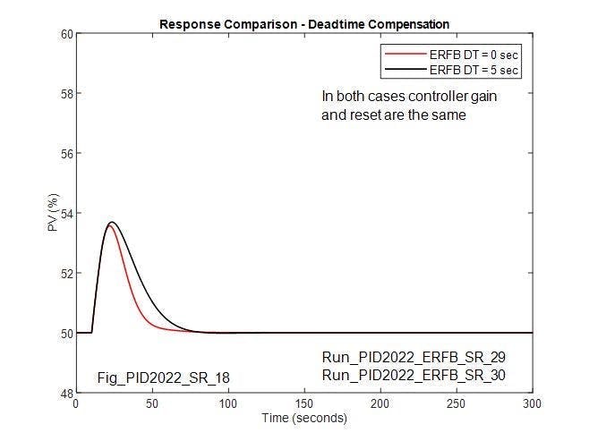
In this case, process deadtime is 5 seconds and process lag is 20 seconds. For the reference case, the controller is tuned for maximum disturbance rejection, which for this lag-dominant process results in a gain of 2 seconds and reset of 15 seconds without overshoot. The reference response is shown in Figure 3, as is the response for the same disturbance when deadtime matching the process deadtime (5 seconds) is included in the ERFB signal. For the reference response, the peak change in PV is 3.7% and the IAE is 7 %sec. When matching deadtime is added in the ERFB signal, the peak change in PV is only slightly different, but the recovery is longer. The IAE increases to 108 %sec. Since the deadtime in the ERFB signal delays the integral action, the increase in the IAE is understandable; however, there’s an opportunity to re-optimize the controller tuning parameters when deadtime is included in the ERFB.

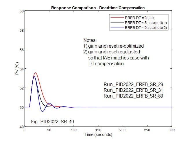
Figure 4 confirms that, with matching deadtime in the ERFB signal, the controller gain and reset can be re-optimized to provide a response for load changes that’s an improvement over what’s obtainable without deadtime in the ERFB signal. With re-optimized control parameters (Kc = 3.7 and Tc = 12 sec), the IAE is 50 %sec, and is significantly lower than what’s obtainable without deadtime in the ERFB. This assertion questions whether the performance of the proportional integral (PI) loop without deadtime compensation can be improved by further adjustment of the PI control parameters, so the IAE matches that of the compensated controller. Figure 4 shows that, while the IAE for the case without deadtime compensation can be reduced to match the case with deadtime compensation, the response obtained is underdamped, and depending on the application and loop interaction, may not be acceptable.

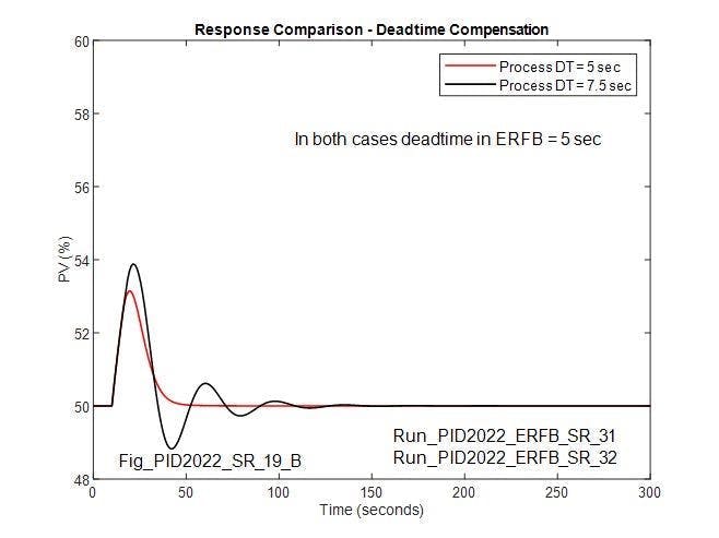
Figure 5 compares the re-optimized response with 5 seconds of process deadtime and matching deadtime in the ERFB, with the response when the process deadtime is increased to 7.5 seconds with the same controller settings. In this case, the loop is oscillatory, not settling for approximately four cycles. The question is whether the effect of an increase in process deadtime is worse when deadtime is included in the ERFB and the controller settings re-optimized than the reference case without deadtime in the ERFB.

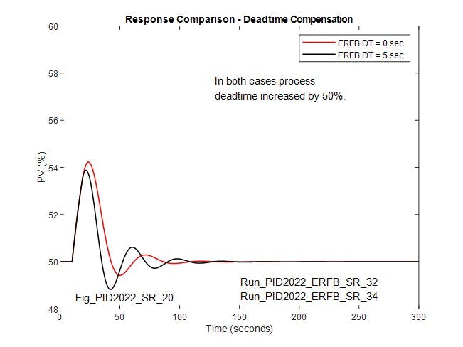
Figure 6 addresses this question, comparing the response of the reference case (when there’s no deadtime in the ERFB) to when 5 seconds deadtime is included in the ERFB and the controller is re-optimized and, in both cases, the process deadtime is increased to 7.5 seconds. While increasing the process deadtime by 50% reduces the damping on both, the effect is greater when deadtime is included in the ERFB for deadtime compensation, and may suggest adapting the ERFB deadtime.

When the deadtime compensated controller is tuned for improved performance over the uncompensated controller, robustness is reduced. This begs the question if there’s a benefit to robustness, when the deadtime-compensated controller is tuned to match the performance of the uncompensated controller. The evidence that follows (Figure 7 and Figure 8) suggests this is the case.
 

Stability margin equal performance—gain

 
Figure 7 compares responses with and without deadtime in the ERFB signal when controller gain is doubled. In both cases, the gain is initially 2.5, but the reset adjusted to 15 sec (from 20 seconds) to approximately match the IAE for the case with deadtime compensation (77 %sec) with the case without deadtime compensation (80 %sec). This allows the stability margin to be objectively compared.

Interestingly, with deadtime compensation (and equal performance with or without deadtime compensation), doubling the gain has less effect on stability than when ERFB deadtime is zero. This may favor using deadtime in the ERFB in applications where the variability in process gain is unpredictable and gain adaptation can’t be applied.   
 

Stability margin equal performance—process deadtime variation

 
When loops are initially tuned to provide equal performance, and when process deadtime is doubled (without a matching change in the ERFB deadtime for the case where deadtime compensation is implemented), the stability when there is deadtime in the ERFB is noticeably better than without deadtime compensation. Similar to process gain variability, where there’s uncertainty in process deadtime, implementing deadtime compensation may be beneficial.

Adding derivative action—lag-dominant process


For a lag-dominant process, when derivative action is added without deadtime compensation, the performance of the deadtime-compensated PI controller can be matched by an optimized PID controller, and can be further improved by adding deadtime compensation to the PID controller to reduce the IAE by 56% of that for the uncompensated PI controller(Figure 9). Derivative action, often overlooked or intentionally avoided due to a reputation gained through improper implementation, should be considered the first of several options for improving loop performance.

Self-regulating process—deadtime dominant

 
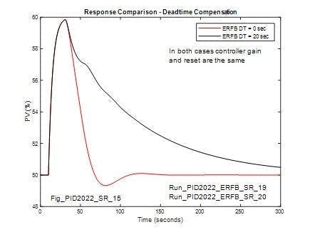
In this case, process deadtime is 20 seconds and process lag is 5 seconds. Without deadtime in the ERFB when the loop is tuned using the Cohen-Coon method, the peak change in PV is approximately the same as it would be without control action since the deadtime is four times the process lag. The PV settles within one cycle, and overshoot is less than 10%. The IAE is 350 %sec. The reference response is shown in Figure 10, which also indicates the response for the same disturbance when deadtime matching the process deadtime (20 seconds) is included in the ERFB signal. 
 
In this case, the response is highly damped, not settling until more than 300 seconds has elapsed. With matching deadtime in the ERFB signal (and no change in controller tuning), the IAE is 950 %sec. This begs the question of whether response with deadtime in the ERFB signal can be better than without the ERFB deadtime, with a re-optimization of the control parameters. 

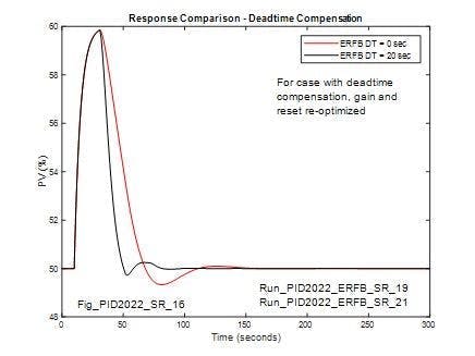
Figure 11 confirms it with matching deadtime in the ERFB signal. The controller gain and reset can be re-optimized to provide a response for load changes that’s an improvement over what’s obtainable without deadtime in the ERFB signal. With re-optimized control parameters (Kc=1.1 and Tc=5sec), the IAE is 240 %sec and is significantly lower than what’s obtainable without deadtime in the ERFB.

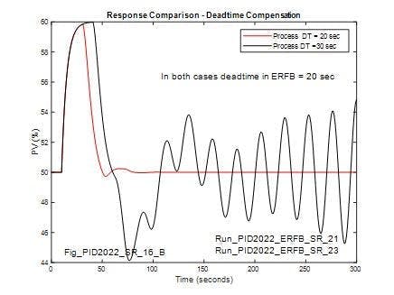
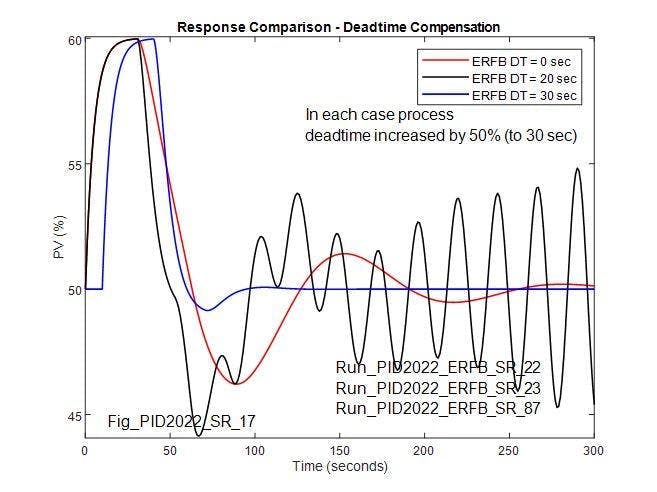
When the compensating deadtime in the ERFB matches the process deadtime and the controller tuning parameters are optimized, the loop performs better than without deadtime compensation. However, as shown Figure 12, this improved performance can’t be achieved without reducing robustness. Figure 12 compares the re-optimized response with 20 seconds process deadtime and matching deadtime in the ERFB to the response when the process deadtime is increased to 30 seconds with the same controller settings. In this latter case, the loop is unstable and the amplitude diverges with time.

Because optimizing the response of the uncompensated controller for a particular process deadtime will be affected by a deadtime change, it’s instructive to compare the response of the uncompensated and compensated controller with an increase in process deadtime. 
 
Referring to Figure 13, in each case, the process deadtime is increased to 30 seconds. While increasing the process deadtime by 50% reduces the stability of the uncompensated and compensated cases, the effect is much greater when deadtime is included in the ERFB for deadtime compensation. However, for the deadtime compensated case, when the deadtime in the ERFB is increased to match the process deadtime, there’s a marked improvement in the response and the IAE (351 %sec) is significantly lower than the uncompensated controller (666 %sec) when the process deadtime increases. This suggests that adjusting one parameter at the compensated controller (ERFB deadtime) can achieve loop stability. However, with the uncompensated controller, controller gain and reset would require adjustment. For cases with 0 seconds and 20 seconds deadtime included in the ERFB, the load disturbance is applied at t = 0 seconds instead of t = 10 seconds (Figure 13). 

Adding derivative action (deadtime-dominant process)

 
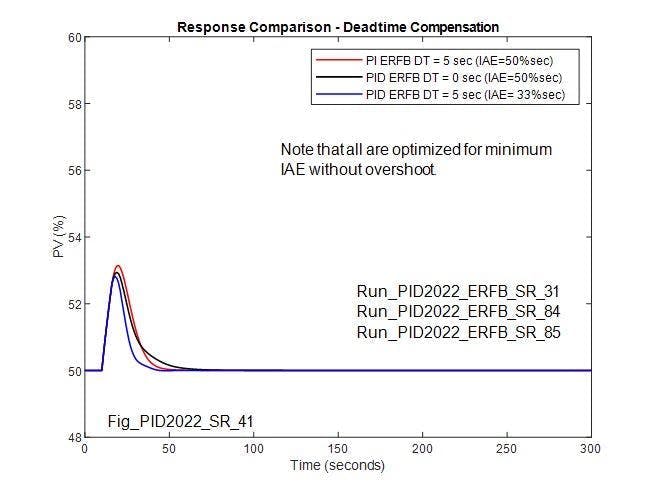
For a deadtime-dominant process, where the deadtime is greater than the lag time, PI performance (IAE) can only be slightly improved by adding derivative action and can’t match the performance with deadtime compensation. Similarly, adding derivative action to the compensated PI controller allows some reduction in IAE, but the additional benefit is so small (less than 4% of IAE) that it might be considered to fall within the practical limits of optimization and be of little benefit.
 
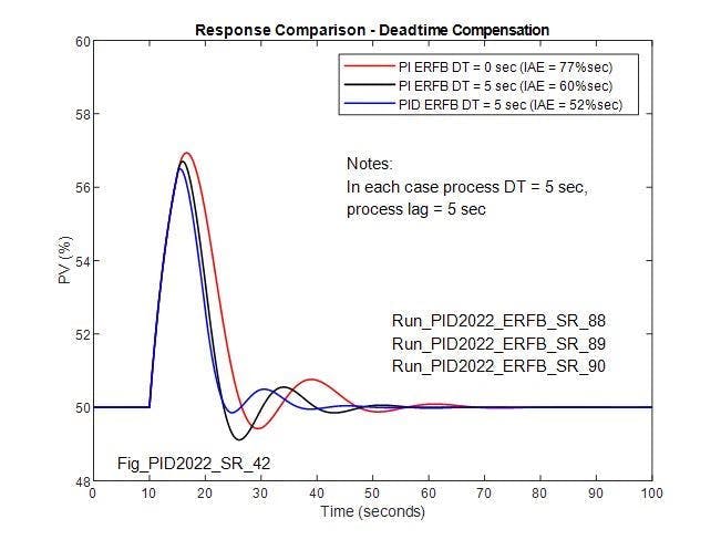
As a rule of thumb, adding derivative action to the compensated controller should be considered when the process deadtime is less than the lag time. Figure 14 shows that, when process deadtime is the same as lag time. it’s still beneficial to add derivative to the controller. Though the benefit is less than when derivative is added for the lag dominant process (Figure 9), it’s still significant.

Integrating process

 
For typical integrating processes involving mass balance, more can be gained by using mass storage to minimize interaction between tandem systems than by using tight control. While tuning the controller for minimum IAE for an integrating process isn’t commonly done, using minimum IAE as a performance objective allows an objective comparison of the response with and without deadtime compensation.  
 
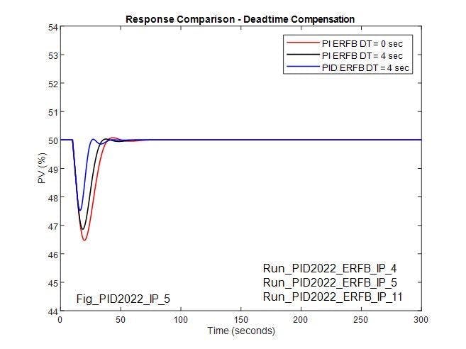
Figure 15 compares the uncompensated PI response with the DT-compensated PI response and PID response. For the PI controller, when deadtime is added to the ERFB and the controller settings are reoptimized, IAE is reduced from 55 %sec to 40 %sec. Though IAE can be further reduced by adding derivative action to the compensated PID controller to reduce IAE to 21% (half of that for the uncompensated PI controller), unless the process deadtime over the process operating range is sensibly constant derivative action is used when the loop is optimized for minimum IAE.  
 
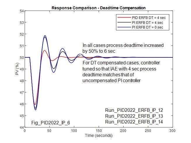
Though the optimized performance of a PI controller with deadtime compensation can be matched by adding derivative action to the uncompensated controller, the stability margin for unaccounted for changes in the process deadtime is much reduced. When the process deadtime is increased by 50%, the amplitude of oscillation is only limited by a limit cycle. Note that there may still be a benefit in adding derivative action when there’s an additional lag in the process, when performance can be improved by pole cancellation.

Figure 16 compares response for process gain and deadtime variation. Interestingly, for a 50% increase in process gain, the response for the uncompensated PI and compensated PI are more oscillatory, but not greatly different from each other, and could be stabilized by a complimentary adaptive change in controller gain. For a 50% increase in process deadtime, the response for the compensated PI controller is more oscillatory than for the uncompensated controller. As with the self-regulating process, when the deadtime in the ERFB is increased to match the process deadtime, there’s a marked improvement in the response, which is notably better than for the uncompensated controller. As with a self-regulating process, this suggests that adjusting just one parameter at the compensated controller (ERFB deadtime)can achieve loop stability, while controller gain and reset with the uncompensated controller would require adjustment.

While a change in process deadtime reduces the stability of the optimized controller, the reduction in stability is less when the controller is tuned for equal performance to the uncompensated PI controller without a matching change in the compensating deadtime. In each case, the compensated controller is tuned, so IAE matches the uncompensated PI controller. For an unaccountable change in process deadtime, the compensated controller with derivative action added provides better (more stable) response when the controller is tuned, so IAE matches the uncompensated PI controller with the original deadtime of 4 seconds. For the compensated PI controller, stability is only slightly better than for the uncompensated PI controller when there’s an unaccounted change in process deadtime.

Conclusions

 
The results indicate that, when the controller implements integral action using filtered positive feedback, and a deadtime matching the process deadtime is included in the ERFB signal, loop performance can be improved if controller tuning parameters are optimized for the deadtime compensated controller. Caution is required in applying this method of deadtime compensation. This is because a change in process deadtime, if unaccounted for by an adjustment in the deadtime in the ERFB, can lead to instability, especially where the process is deadtime-dominant. 
 
The automatic adjustment of the deadtime block can be set up to account for changes in loop deadtime. Deadtime is the easiest and fastest dynamic parameter to identify from changes in setpoint and superimposed pulses in the PID output. In applications where the dependence of process deadtime on plant operating conditions is well understood, deadtime can be computed online. When the deadtime in the ERFB can be suitably adjusted, there’s a greater opportunity for performance improvement. 
For both self-regulating and integrating processes, control loop stability margin is improved and is better than for the uncompensated controller, when the deadtime compensated controller is tuned more conservatively to match the performance of the uncompensated controller (equal IAE). 
 
For loop performance improvement of lag-dominant processes, the benefit of adding derivative action should not be overlooked, either as a means of improving the response of the uncompensated controller or further improving responses of compensated controllers. When properly implemented, i.e. implemented as a filtered derivative acting on the process variable rather than error, amplifying process noise can be minimized and unwarranted action for setpoint step change can be avoided.
About the Author

Peter Morgan

Peter Morgan has 40 years experience designing and commissioning control systems for the power and process industries. He's an ISA senior member and contributing member of the ISA 5.9 PID committee.

About the Author

Greg McMillan | Columnist

Greg K. McMillan captures the wisdom of talented leaders in process control and adds his perspective based on more than 50 years of experience, cartoons by Ted Williams and Top 10 lists.

Sponsored Recommendations

Make Effortless HMI and PLC Modifications from Anywhere

The tiny EZminiWiFi is a godsend for the plant maintenance engineers who need to make a minor modification to the HMI program or, for that matter, the PLC program. It's very easy...

The Benefits of Using American-Made Automation Products

Discover the benefits of American-made automation products, including stable pricing, faster delivery, and innovative features tailored to real-world applications. With superior...

50 Years of Automation Innovation and What to Expect Next

Over the past 50 years, the automation technology landscape has changed dramatically, but many of the underlying industry needs remain unchanged. To learn more about what’s changed...

Manufacturing Marvels Highlights Why EZAutomation Is a Force to Be Reckoned With

Watch EZAutomation's recent feature on the popular FOX Network series "Manufacturing Marvels" and discover what makes them a force to be reckoned with in industrial automation...